Motor terminal identification and connection diagram
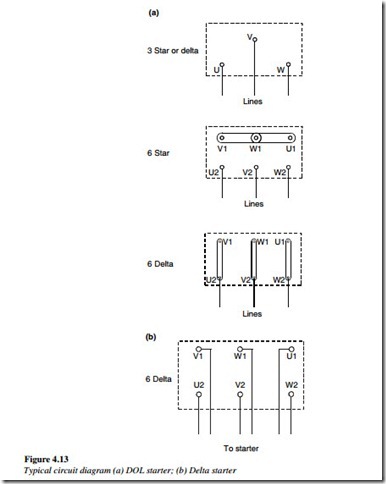
Usually, the motor terminal connection diagram is given on the motor. For a three-phase motor, three winding end connections are shown – U1 and U2, V1 and V2, and W1 and W2.
Motor terminals and connection diagrams for Autotransformer or DOL starting with three- or six- leads connection are shown in Figure 4.13(a).
Terminal connection diagram
DOL or autotransformer starting with three or six leads. Number of leads connection
Motor terminals and connection diagrams for star–delta starting with six-leads connection is shown in Figure 4.13(b).
Similarly, for a DC motor, field connections are indicated as F1 and F2 while armature winding is shown as A1 and A2. If the DC motor is of a series-type or a compound type, then the series winding leads are shown as S1 and S2.
