INTERCONNECTION WITH THE GRID
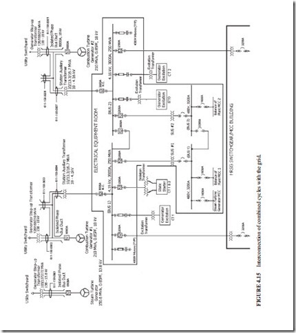
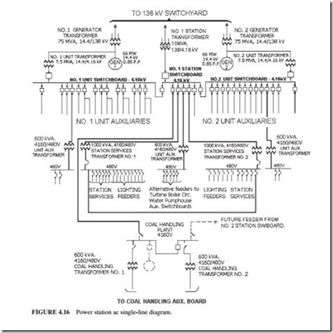
Figures 4.15 and 4.16 illustrate interconnections of power plants with the grid. The trans- former that connects the plant with the grid is normally called the main output transformer (MOT) or generator step-up transformer. The transformer that connects the output of the generator with the plant itself (feeding power back to the plant) is called the unit service transformer (UST) or station auxiliary transformer. The rating of the UST is normally about 6 to 7 percent of the MOT. The transformer that connects the grid to the station loads (allow- ing power to be fed back to the unit) is called the station service transformer (SST). The design philosophy for supplying power to the loads in the plant varies. Some power plants supply one-half of their loads through the UST and the other half through the SST. However, modern power plants have opted to supply all their power through the UST. They use the incoming power through the SST as backup. In the plants where the plant loads are supplied equally from the UST and SST (Fig. 4.16), the tie breakers connecting the buses inside the plant close when the unit is disconnected from the grid. This is done to ensure that the loads inside the plant continue to be supplied with power when the unit is taken off line.
Some plants install the generator breaker before the line feeding power from the output of the generator back into the plant. In this design, the plant loads are supplied from another source (e.g., the grid) when the breaker opens. Other plants install the generator breaker after the line feeding power from the output of the generator back into the plant. When the genera- tor breaker opens (due to a load rejection), a significant load shedding occurs (about 94 per- cent of the load is taken off within a fraction of a second). This results in a significant reduction in countertorque on the generator shaft (about 94 percent reduction). Since the driving torque from the turbine has not changed, the turbine-generator shaft will accelerate. The governing system will limit the overspeed normally to 8 percent. However, since the generator is still sup- plying the plant loads at higher frequency (up to 8 percent higher), the synchronous speed of the motors inside the plant will increase. The currents pulled by these motors from the power supply will increase. This results in tripping of these motors in some plants on overload.
Transformers are used inside the plant to provide power to the loads requiring lower voltage. Some steam power plants use separate gas turbines as backup power (standby generators). They feed the 4-kV and 600-V buses inside the plant when the normal power from the UST and SST is lost. This type of power is considered more reliable than the power sup- plied from the UST or SST. Most plants use large battery banks to supply emergency loads (e.g., turbine emergency dc lube oil pump, generator stator emergency dc water cooling pump, and generator emergency dc seal oil pump). Some plants use inverters to supply emergency ac power from the battery bank to plant loads. The reliability of power supplies in descending order is as follows:
1. Power from the battery banks (dc or ac through inverters) (most reliable)
2. Standby generators
3. Power through UST or SST (least reliable).

