Time delay relays can be divided into two general classifications: the on-delay relay, and the off-delay re- lay. The on-delay relay is often referred to as DOE, which stands for “Delay On Energize.” The off-delay relay is often referred to as DODE, which stands for “Delay On De-Energize.”
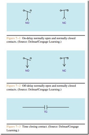
Timer relays are similar to other control relays in that they use a coil to control the operation of some number of contacts. The difference between a control relay and a timer relay is that the contacts of the timer relay delay changing their position when the coil is energized or de-energized. When power is connected to the coil of an on-delay timer, the contacts delay chang- ing position for some period of time. For this example, assume that the timer has been set for a delay of 10 seconds. Also assume that the contact is normally open. When voltage is connected to the coil of the on-delay timer, the contacts will remain in the open position for 10 seconds and then close. When voltage is removed and the coil is de-energized, the contact will immediately change back to its normally open position. The contact symbols for an on-delay relay are shown in Figure 7 – 1.
The operation of the off-delay timer is the opposite of the operation of the on-delay timer. For this example, again assume that the timer has been set for a delay of 10 seconds, and also assume that the contact is nor- mally open. When voltage is applied to the coil of the off-delay timer, the contact will change immediately from open to closed. When the coil is de-energized, however, the contact will remain in the closed position for 10 seconds before it reopens. The contact symbols for an off-delay relay are shown in Figure 7 – 2. Time- delay relays can have normally open, normally closed, or a combination of normally open and normally closed contacts.
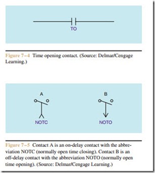
Although the contact symbols shown in Fig- ures 7 – 1 and 7– 2 are standard NEMA symbols for on-delay and off-delay contacts, some control schemat- ics may use a different method of indicating timed contacts. The abbreviations TO and TC are used with some control schematics to indicate a time-operated contact. TO stands for time opening, and TC stands for time closing. If these abbreviations are used with stan- dard contact symbols, their meaning can be confusing. Figure 7 – 3 shows a standard normally open contact symbol with the abbreviation TC written beneath it. This contact must be connected to an on-delay relay if it is to be time delayed when closing. Figure 7 – 4 shows the same contact with the abbreviation TO beneath it. If this contact is to be time delayed when opening, it must be operated by an off-delay timer. These abbreviations can also be used with standard NEMA symbols as shown in Figure 7 – 5.
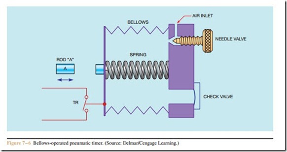
Pneumatic, or air timers, operate by restricting the flow of air through an orifice to a rubber bellows or diaphragm. Figure 7– 6 illustrates the principle of operation of a simple bellows timer. If rod “A” pushes against the end of the bellows, air is forced out of the bellows through the check valve as the bellows con- tracts. When the bellows is moved back, contact TR changes from an open to a closed contact. When rod “A” is pulled away from the bellows, the spring tries to return the bellows to its original position. Before the bellows can be returned to its original position, however, air must enter the bellows through the air in- let port. The rate at which the air is permitted to enter the bellows is controlled by the needle valve. When the bellows returns to its original position, contact TR re- turns to its normally open position.
Pneumatic timers are popular throughout industry because they have the following characteristics:
A. They are unaffected by variations in ambient temperature or atmospheric pressure.
B. They are adjustable over a wide range of time periods.
C. They have good repeat accuracy.
D. They are available with a variety of contact and timing arrangements.
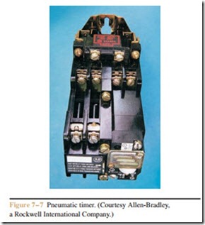
Some pneumatic timers are designed to permit the timer to be changed from on-delay to off-delay, and the con- tact arrangement to be changed to normally opened or normally closed (Figure 7– 7). This type of flexibility is another reason for the popularity of pneumatic timers.
Many timers are made with contacts that operate with the coil as well as time delayed contacts. When these contacts are used, they are generally referred to as instantaneous contacts and indicated on a schematic diagram by the abbreviation INST. printed below the contact (Figure 7 – 8). These instantaneous contacts change their positions immediately when the coil is energized and change back to their normal positions immediately when the coil is de-energized.


