TIMED STARTING FOR THREE MOTORS
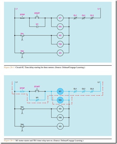
A machine contains three large motors. The current surge to start all three motors at the same time is too great for the system. Therefore, when the machine is to be started, there must be a delay of 10 seconds be- tween the starting of each motor. Circuit #2, shown in Figure 20 – 1, is a start-stop, push-button control that controls three motor starters and two time-delay relays. The circuit is designed so that an overload on any motor will stop all motors.
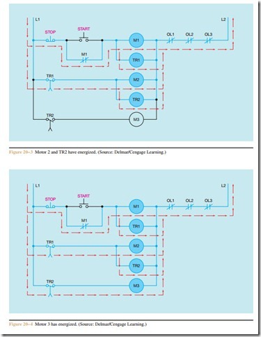
When the START button is pressed, a circuit is completed through the START button, M1 motor starter coil, and TR1 relay coil. When coil M1 energizes, motor #1 starts and auxiliary contact M1, which is parallel to the START button, closes. This contact maintains the current flow through the circuit when the START button is released (Figure 20 – 2).
After a 10-second interval, contact TR1 closes. When this contact closes, a circuit is completed through motor starter coil M2 and timer relay coil TR2. When coil M2 energizes, motor #2 starts (Figure 20 – 3).
Ten seconds after coil TR2 energizes, contact TR2 closes. When this contact closes, a circuit is completed to motor starter coil M3, which causes motor #3 to start (Figure 20 – 4).
If the STOP button is pressed, the circuit to coils M1 and TR1 is broken. When motor starter Ml de- energizes, motor #1 stops and auxiliary contact Ml opens. TR1 is an on-delay relay; therefore, when coil TR1 is de-energized, contact TR1 opens immediately.
When contact TR1 opens, motor starter M2 de-energizes, which stops
TR2 opens immediately. This breaks the circuit to motor starter M3. When motor starter M3 de-energizes, motor #3 stops. Although it takes several seconds to explain what happens when the STOP button is pressed, the action of the relays is almost instantaneous. If one of the overload contacts opens while the circuit is energized, the effect is the same as pressing the STOP button. After the circuit stops, all contacts re- turn to their normal positions, and the circuit is the same as the original circuit shown in Figure 20 – 1.
Review Questions
1. Explain the operation of circuit #2 (Figure 20 – 1) if contact M1 did not close.
2. Explain the operation of circuit #2 (Figure 20 – 1) if relay coil TR2 were burned out.
3. Refer to circuit #2, shown in Figure 20–1. Assume that both times are set for a delay of 5 seconds. When the START button is pressed, motor #1 starts running immediately. After a delay of 10 seconds, motor #3 starts running, but motor #2 never starts. Which of the following could cause this problem?
a. TR1 coil is open.
b. M2 starter coil is open.
c. TR2 coil is open.
d. OL2 contact is open.
4. Refer to circuit #2, shown in Figure 20 – 1.
Assume that the timers are set for a delay of 5 sec- onds. When the START button is pressed nothing happens. No motors start running for a period of
1 minute. Which of the following could not cause this problem?
a. M1 holding contacts did not close.
b. the STOP push-button is open.
c. OL1 contact is open.
d. M2 coil is open.

