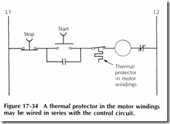
A motor may have a thermal protector in the windings to sense motor overheating. This thermal protector may be required to be wired in as a part of the control circuit wiring. In this case, the thermal protector is simply wired in series with the control circuit. If the thermal protector opens, the control circuit is broken and the motor stops. A ladder diagram of a thermal protector in a control circuit is shown in Figure 17 34
CONTROL DEVICES
Common control ladder diagrams and schematic wiring diagrams use some basic symbols and terminology. Switches and contacts are the basic control components, and they take several different forms. Switches and contacts may be operated mechanically by a timer or by some change in condition, such as temperature, pressure, flow, liquid level, or humidity
Switches and contacts are described by the number of poles and the number of throws. The number of poles is the number of paths into a switch or contact. The number of throws is the number of paths leaving each pole
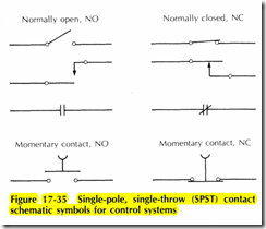
It must also be known if the switch or contact is i the open or closed position when it is in the unactivate state. If the switch or contact is open when in the unacti vated state, it is considered to be normally open (NO: when it is in the opposite position, it is said to be nm mally closed (NC). Common single pole, single throw (SPST) switch and contact symbols are shown in Figure 17 35.
A single pole, double throw (SPDT) switch or contact has one input wire and two output wires. One is normally open, and the other is normally closed. Many control devices use this type of contact so that one device can be used for many different purposes. Both output wires may be used, but often only one is used. Common single pole, double throw contacts are shown in Figure 17 36. A 3 way toggle switch, for example, is actually a single pole, double throw switch.
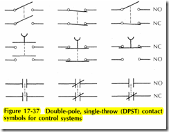
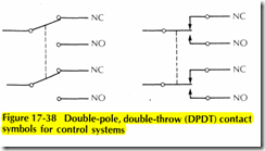
Another very common and versatile switch or contact arrangement is the double pole, single throw (DPST) contact. Some of the most common types are shown in Figure 17 37. The double pole, double throw (DPDT) contacts are common with control switches and timing relays, Figure 17 38
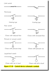
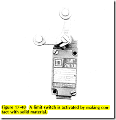
The common types of switches and contacts are incorporated into various types of control devices. Only single pole, single throw contacts are shown in the following diagrams; however, the other types of contacts discussed previously are available. Control device schematic symbols that are frequently used are shown in Figure 17 39. A limit switch is a device which is activated when something presses against the lever arm or actuator. It may be of the two position type or the momentary . contact type, Figure 17 40. Limit switches are frequently used to sense material flow in an automatic materials handling or processing system, such as a grain drying system or an animal feeding system
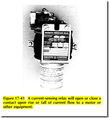
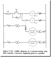
A current sensing relay is a magnetic coil which closes a set of contacts when the current reaches a preset level, Figure 17 41. An application of a current sensing relay is a feed grinder with an automatic conveyer supplying grain to the grinder. As long as the grinder is fully loaded, the conveyer is off. As soon as the grinder loadcurrent drops, indicating the grinder is not full, the current sensing relay closes the contacts and turns on the conveyer. A ladder diagram of the control system is shown in Figure 17 42
Time delay relays are used on many types of processes or machines where a time delay of a few seconds or minutes is desired. A typical example is a grain dryer control. The time delay relay consists of one or more contacts and a timing device. Once power is supplied to the timing relay, it begins timing. After the preset time period, the contact or switch is activated to the alternate position. The schematic diagram for a time delay relay is shown in Figure 17 43. After the timing is complete, the switch moves in the direction of the arrow at the bottom of the schematic symbol. Some types of time delay relays are shown in Figure 17 44
A typical timing relay may have an eight pin socket, Figure 17 45. The timer voltage can be specified, but 120 V is common. This timing relay is a double pole, double throw type. Only the required contacts are used. Figure 17 46 shows a ladder diagram for two electric motors, one of which is operated with a timing relay
The start stop station activates motor A and the timer of the timing relay. After a 30 second delay, motor B operates
