THE VOLTAGE REGULATOR
Background
Early voltage regulators used mechanical components. They had a large deadband and long response time and required regulator maintenance. Modern automatic voltage regulators
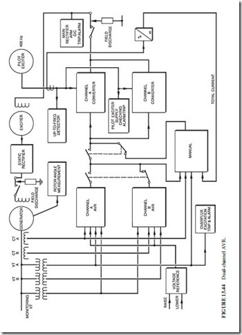
use integrated circuits or digital microprocessor techniques. Figure 13.44 illustrates a modern dual-channel arrangement.
System Description
The main function of the AVR is to maintain constant generator terminal voltage while the load conditions are changing. A dual-channel AVR with manual backup is normally used. The reliability of this design is high because the loss of one channel does not affect the operational performance. The faulty channel can be repaired during operation.
The Regulator
The AVR is a closed-loop controller. It compares a signal proportional to the terminal volt- age of the generator with a steady voltage reference. The difference (error) is used to con- trol the exciter output.
When the load changes, the error increases. The channel A AVR applies a proportional- integral-derivative (PID) algorithm to the error and provides a corrective signal. This sig- nal is amplified by the channel A converter. It is then sent to vary a field resistance. The excitation current will change, and the terminal voltage will change accordingly. It is crit- ical to have a fast, stable response from the AVR. Special signal conditioning networks are introduced in the PID control to prevent instability. Accurate tuning (selection of PID coef- ficients) of the voltage response is achieved by having adjustable time constants.
The AVR receives the generator terminal voltage signal through its own interposing voltage transformer. The voltage signal is rectified and filtered before being compared with the reference voltage.
Auto Follow-up Circuit
In a dual-channel AVR, both channels can be active simultaneously. Each channel provides one-half of the excitation requirements. An alternative design allows one channel to be active while the other follows passively. If a channel trips, the other picks up the full exci- tation requirement in a “bumpless” manner. A follow-up circuit is used to achieve this func- tion. It tracks the primary (or active) channel and drives the output of the standby channel to match the output of the primary channel.
Manual Follow-up
This is a manual follow-up system similar to the auto follow-up system. When the AVR fails, the manual control takes over in a bumpless manner.
AVR Protection
The AVR plays a critical role in the overall protection scheme of the generator because it con- trols the suppression of the field after faults. The generator should also be protected against AVR component failure which could jeopardize its operation. An overvoltage relay monitors the terminal voltage of the generator. If the voltage exceeds a safe level, the field current is reduced in minimum time. This relay is only active when the generator is not synchronized.
An overfluxing relay is also active only during unsynchronized operation. If the safe volt- age/frequency ratio is exceeded, the generator transformer could be overfluxed. A special relay detects this condition and initiates an alarm. The AVR controls reduce excitation to a safe level. If this condition persists, the excitation is tripped. A component failure within the AVR results in over- or underexcitation. The active channel output is compared with the minimum and maximum field currents. When a limit is exceeded for a few seconds, the channel is tripped.
The Digital AVR
The use of microprocessors in AVRs has many advantages. The reliability will increase due to the reduction of the number of components. Most of the control logic in solid-state AVRs is done by electromechanical relays. These relays will be replaced by a specified micro-
GENERATOR COMPONENTS, AUXILIARIES, AND EXCITATION 13.53
processor software. The cost of microprocessor-based AVRs is lower than that of conven- tional solid-state AVRs. This is due to the replacement of the customized printed circuit boards by standard memory circuits. However, the main advantage of microprocessor- based AVRs lies in the wide range of sophisticated control features. One type of controller, called the adaptive regulator, is capable of adjusting its structure to accommodate the changing plant conditions.
Excitation Control
Modern excitation equipment includes a number of limiter circuits. These limiters operate as parallel controllers. Their signals replace the generator voltage, which is the controlled variable when the input signals exceed predefined limits.
Rotor Current Limiter
All exciters have the capability of supplying a field current significantly higher than the one required during normal operation. This field forcing capability or margin is needed during a fault to increase the reactive power. However, the duration of the increase in current must be limited to prevent overheating of the rotor, which would lead to degradation of the insula- tion system. During a system fault, the AVR boosts excitation. This situation lasts normally milliseconds before the circuit breaker clears the fault. However, the backup protection is allowed to last up to 5 s (or more). After this delay, the rotor current limit circuit sends a sig- nal that overrides the one from the AVR, causing a reduction in excitation current.
Overfluxing Limit
Modern AVRs have overfluxing limiter circuits in addition to the overfluxing protection circuit. The overfluxing limiter circuit is a closed-loop controller. It monitors the volt- age/frequency ratio when the generator is not synchronized. When a predefined ratio is exceeded, the limiter reduces excitation.

