Objectives
After studying this unit, the student will be able to :
• Discuss the operation of an SCR in a de circuit
• Discuss the operation of an SCR in an ac circuit
• Draw the schematic symbol for an SCR
• Discuss phase shifting
• Test an SCR with an ohmmeter
• Connect an SCR in a circuit
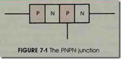
The silicon-controlled rectifier (SCR) is often referred to as a PNPN junction because it is made by joining four layers of semiconductor material, figure 7-1. The schematic symbol for the SCR is shown in figure 7-2. Notice that the symbol for the SCR is the same as the symbol for the diode except that a gate lead has been added. Case styles for SCRs are shown in figure 7-3.
The SCR is a member of a family of devicesknown as thyristors. Thyristors are digital devices in that they have only two states, on and off. The SCR is used when it is necessary for an electronic device to control a large amount of power. For ex ample, assume that an SCR has been connected in a circuit as shown in figure 7-4. When the SCR is turned off, it will drop the full voltage of the cir cuit and 200 volts will appear across the anode and cathode. Although the SCR has a voltage drop of 200 volts, there is no current flow in the circuit. The SCR does not have to dissipate any power in this condition (200 volts X 0 amperes = 0 watts). When the push button is pressed, the SCR turns on, producing a voltage drop across its anode and cathode of about 1 volt. The load resistor limits the circuit current to 2 amperes Since the SCR now has a voltage drop of 1 volt and 2 amperes  of current flowing through it, it must dissipate 2 watts of heat (1 volt X 2 amperes
= 2 watts). Notice that although the SCR is dis sipating only 2 watts of power, it is controlling 400 watts of power.
THE SCR IN A DC CIRCUIT
When an SCR is connected in a de circuit as shown in figure 7-4, the gate will turn the SCR on, but it will not turn the SCR off. To turn the an ode-cathode section of the SCR on, the gate must be connected to the same polarity as the anode. Once the gate has turned the SCR on, the SCR will remain on until the current flowing through the anode-cathode section drops to a low enough level to permit the device to turn off. The amount of current required to keep the SCR turned on is called the holding current.In figure 7-5 assume that resistor R1 has been adjusted to its highest value and resistor R2 has been adjusted to its lowest or 0 value. When switch S1 is closed, no current will flow through the anode-cathode section of the SCR because re sistor R1 prevents the amount of current needed to trigger the device from flowing through the gate-cathode section of the SCR. If the value of resistor R1 is slowly decreased, current flow through the gate-cathode section will slowly in crease. When the gate reaches a certain level, as sume 5 rnA for this SCR, the SCR will fire, or turn on. When the SCR fires, current will flow through the anode-cathode section and the voltage drop across the device will be about 1 volt. Once the SCR is turned on, the gate has no control over the device. It could be disconnected from the anode without affecting the circuit. When the SCR fires, the anode-cathode section becomes a short circuit and current flow is limited by resistor R3.
Now assume that resistor R2 is slowly in creased in value. When the resistance of R2 is slowly increased, the current flow through the an ode-cathode section will slowly decrease. Assume that when the current flow through the anode cathode section drops to 100 rnA, the device sud denly turns off and the current flow drops to 0. This SCR requires 5 rnA of gate current to turn it on, and has a holding current value of 100 rnA.
THE SCR IN AN AC CIRCUIT
The SCR is a rectifier; when it is connected in an ac circuit, the output is direct current. The SCR operates in the same manner in an ac circuit as it does in a de circuit. The difference in opera tion is caused by the ac waveform falling back to 0 at the end of each half cycle. When the ac wave form drops to 0 at the end of each half cycle, the SCR turns off. This means that the gate must retrigger the SCR for each cycle it is to conduct, figure 7-6.
Assume that the variable resistor connected to the gate has been adjusted to permit 5 rnA of current to flow when the voltage applied to the anode reaches its peak value. When the SCR turns on, cur rent will begin flowing through the load resistor when the ac waveform is at its positive peak. Current will continue to flow through the load until the de creasing voltage of the sine wave causes the current to drop below the holding current level of 100 rnA. When the current through the anode-cathode sec tion drops below 100 rnA, the SCR turns off and all current flow stops. The SCR will remain turned off when the ac waveform goes into its negative half cy cle because during this half cycle the SCR is reverse biased and cannot be fired.
If the resistance connected in series with the gate is reduced, a current of 5 rnA will be reached before the ac waveform reaches its peak value , figure 7-7. This will cause the SCR to fire earlier· in the cycle. Since the SCR fires earlier in the cycle, current is permitted to flow through the load resis tor for a longer period of time, which produces a higher average voltage drop across the load. If the resistance of the gate circuit is reduced again as shown in figure 7-8, the 5 rnA of gate current needed to fire the SCR will be reached earlier than in figure 7-7. Current will begin flowing through the load sooner than before, which will permit a higher average voltage to be dropped across the load.
Notice that this circuit enables the SCR to control only half of the positive waveform. The latest the SCR can be fired in the cycle is when the ac waveform is at 90° or peak. If a lamp were used as the load for this circuit, it would burn at half brightness when the SCR first turned on. This control would permit the lamp to be operated from half brightness to full brightness, but it could not be operated at a level less than half brightness.
PHASE SHIFTING THE SCR
The SCR can control all of the positive wave form through the use of phase shifting. As the term implies, phase shifting means to shift the phase of one thing in reference to another. In this instance, the voltage applied to the gate must be shifted out of phase with the voltage applied to the anode. Al though there are several methods used for phase shifting an SCR, it is beyond the scope of this text to cover all of them. The basic principles are the same for all of the methods, however, so only one method is covered.
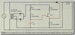
To phase shift an SCR, the gate circuit must be unlocked or separated from the anode circuit. The circuit shown in figure 7-9 will accomplish this. A 24-volt, center-tapped transformer is used to isolate the gate circuit from the anode circuit. Diodes D 1 and D2 are used to form a two-diode type of full-wave rectifier to operate the UJT cir cuit. Resistor R1 is used to determine the pulse rate of the UJT by controlling the charge time of capacitor Cl. Resistor R2 is used to limit the cur rent through the emitter of the UJT if resistor R1 is adjusted to 0 ohms. Resistor R3 limits current through the base 1-base 2 section when the UJT turns on. Resistor R4 permits a voltage spike or pulse to be produced across it when the UJT turns on and discharges capacitor Cl. The pulse pro duced by the discharge of capacitor C1 is used to trigger the gate of the SCR.
Since the pulse of the UJT is used to provide a trigger for the gate of the SCR, the SCR can be fired at any time regardless of the voltage applied to the anode. This means that the SCR can now be fired as early or late during the positive half cycle as desired because the gate pulse is deter mined by the charge rate of capacitor Cl. The voltage across the load can now be adjusted from 0 to the full applied voltage.
TESTING THE SCR
The SCR can be tested with an ohmmeter (see Procedure 4 in the Appendix) . To test the SCR, connect the positive output lead of the ohmmeter to the anode and the negative lead to the cathode. The ohmmeter should indicate no continuity. Touch the gate of the SCR to the an ode. The ohmmeter should indicate continuity through the SCR. When the gate lead is removed from the anode, conduction may stop or continue depending on whether or not the ohmmeter is supplying enough current to keep the device above its holding current level. If the ohmmeter indicates continuity through the SCR before the gate is touched to the anode, the SCR is shorted. If the ohmmeter will not indicate continuity through the SCR after the gate has been touched to the anode, the SCR is open.
REVIEW QUESTIONS
1. What do the letters SCR stand for?
2. If an SCR is connected to an ac circuit, will the output voltage be ac or de?
3. Briefly explain how an SCR operates when connected to a de circuit.
4. How many layers of semiconductor material are used to construct an SCR?
5. SCRs are members of a family of devices known as thyristors. What is a thyristor?
6. Briefly explain why thyristors have the ability to control large amounts of
power.
7. What is the average voltage drop of an SCR when it is turned on?
Explain why an SCR must be phase shifted.


