A permanent magnet DC motor can withstand vibration and many other adverse conditions better than a motor with wound field coils.
The armature is the only electrical circuit in the permanent magnet DC motor. The stator has permanent magnets fastened to its shell. The permanent magnets aren’t as thick as field coils, so the motor has a smaller diameter than the wound field coil motor.
Operation of the Permanent Magnet Motor
The permanent magnet motor operates much like a shunt motor. The magnets furnish torque and counter-voltage (like the coils of the shunt field).
The strength of the permanent magnets, however, can’t be controlled. If the magnets lose strength, the motor will run faster than nameplate RPM. Loads that require more horsepower (as the speed increases) cause the armature to overheat and fail.
Restoring Magnetism
If a permanent magnet motor runs more than 10 percent above nameplate RPM (with no load), its magnets need to be remagnetized (re-gaussed). Magnetism in a weak magnet can be restored with a stronger magnet. An extremely strong magnet will bring a weak magnet to full strength almost instantly.
Electric motor repair centers use special equipment (a re-gaussing unit and an electromagnet) to re-gausse weak magnets. The re-gaussing unit contains a large number of DC capacitors. When fully charged these capacitors can—for an instant—discharge a very high DC current.
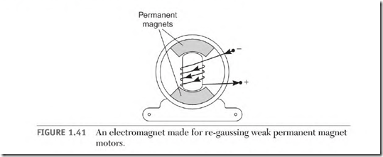
An electromagnet is designed to closely fit the bore of the permanent magnet motor. It’s placed in the motor’s bore, as illustrated in Fig. 1.41. The re-gaussing unit’s capacitors are discharged through the electromagnet’s coil—once or twice—creating very strong magnetism. The motor’s magnets are almost instantly re-gaussed. The motor is then assembled and test run.
Large permanent magnet motors have magnetizing field coils wrapped around the permanent magnets. These field coils demagnetize and remagnetize the permanent magnets. (It’s very hard to remove the armature unless the permanent magnets have been demagnetized.) After the motor has been repaired and the motor reassembled, DC is applied to the magnetizing field until the permanent magnets are remagnetized. The permanent magnets have full strength when the motor runs less than 10 percent above nameplate RPM with no load. (The magnetizing field leads are separated and insulated when they aren’t in use.)
The stator’s permanent magnets will lose power if the armature is left out of the stator for an extended time. A closefitting rotor, a piece of iron, or another armature should be inserted into the bore. This completes the magnetic path. It’s similar to the keeper that is used on horseshoe magnets. Magnetism can also be weakened if the motor is reversed (plugged) while running. Another suspected cause is rough handling.
The Series Motor
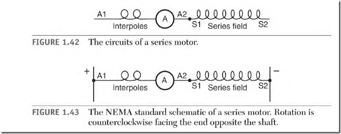
The series motor has two circuits, the armature and interpoles, Al and A2 ![]() and the series field, Sl and S2 (Fig. 1.42).
and the series field, Sl and S2 (Fig. 1.42).
Figure 1.43 shows the NEMA standard connection for counterclockwise rotation facing the end opposite the shaft.
As shown in Fig. 1.43 the two circuits are connected in series with each other. All of the armature amperes pass through the series field. This makes it necessary to construct the series field coils with wire large enough to carry the full amperes of the motor.
The large wire used in the series field coils makes it a very lowresistance circuit. Amperes through the series field are limited by the counter-voltage developed in the armature. A series field (Sl and S2) should never have the motor’s rated DC voltage applied to it.
Operation of the Series Motor
The series motor has very high starting torque. The ampere demand of the armature is very high (at 0 RPM). The same high amperes flow through the series field, resulting in very strong starting torque.
As the armature accelerates, it develops counter-voltage. The countervoltage lowers the amperes through the armature and the series field. Fewer amperes through the series field lowers the number of lines of force. This lowers the amount of counter-voltage and torque.
The counter-voltage never becomes high enough to control the speed of the series motor, as it does with the shunt motor. Only the load will keep this motor from destroying itself because of high RPM. (Technically, it has no top speed.) A large series motor must have “no-load protection” in its control.
The load is usually direct drive, so this motor must always be loaded.
The starter for an automobile engine is a series motor. Although it’s small, it has very high starting torque.
Power tools also have series motors. Gear and bearing friction and a cooling fan keep them from developing excessive RPM.
The Compound DC Motor
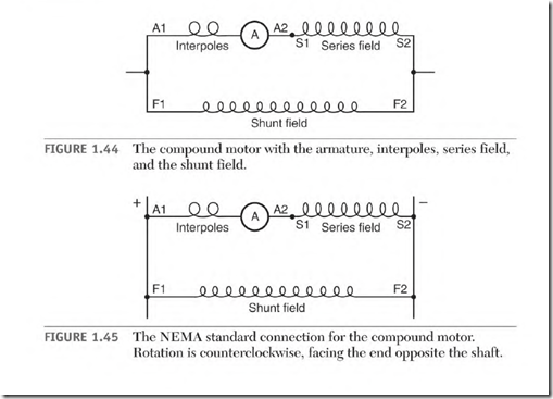
The compound DC motor has three circuits (Fig. 1.44), the armature and interpoles (Al and A2), the shunt field (Fl and F2), and the series field (Sl and S2). Figure 1.45 shows the NEMA standard connection for counterclockwise rotation facing the end opposite the shaft.
The Armature and Interpoles
As shown earlier, the armature and interpole leads are identified as Al and A2. The armature windings produce all of the motor’s torque output. The interpoles ensure good commutation.
The Series Field
As described earlier, the series field (Sl and S2) is connected in series with Al and A2. The armature current goes through the series field, adding magnetic strength to the pole iron. This stabilizes the motor’s speed when the load varies.
Operation of the Compound Motor Connected Cumulative Compound
The shunt field is connected in parallel with the armature and series field circuit. Unloaded, the motor starts and accelerates to a speed that
is determined by the shunt field. (The shunt field produces enough countervoltage to stabilize the speed.)
As the load is applied, the amperes increase in the armature. The armature current goes through the series field, producing lines of force. These lines of force are added to the shunt field lines of force, resulting in an increase in field strength and torque. The added strength of the series field stabilizes the RPM as the load is applied. Unlike the shunt motor, this motor doesn’t slow as the load increases.
The number of turns of wire in the series field directly affects the amount of stabilizing done.
The flat compound design has enough turns in the series field to raise the RPM as the load is applied. When rated load is reached, the RPM stabilizes at nameplate value. The over-compound design has enough turns in the series field to raise the RPM to a higher value at full load than at no load. This is the more popular design. The motor’s control gives it a wide speed range.
The Stabilized Shunt Motor
The stabilized shunt design has very few turns in the series field. The series field is connected differential compound. As the load increases, armature and series field current increases.
The resulting series field magnetism cancels some of the magnetism of the shunt field. This lowers the counter-voltage very quickly and allows more amperes to flow in the armature. The motor will react quickly to sudden load changes. Some efficiency is lost with this design.


