Costly mistakes can be avoided if the technician understands the two types of connections used in the nine-lead motor. Testing can be done accurately and with confidence if the connections are fully understood.
The dual-voltage nine-lead three-phase motor is internally connected wye or delta. Data found between lead numbers are very different in the two connections. Some winding failures in a wye-connected motor will have a different look from those in a delta-connected motor—even when both have the same basic problem. Test results will also be different.
It’s important to identify the cause of burned windings. They will have a different appearance in all these situations: single-phase burnout, overload, unbalanced voltage, and voltage spikes. (Voltage spike damage occurs more often in motors controlled by variable-hertz drives.) These problems are all caused by in-plant faults that require correction. A replacement motor can fail—sometimes immediately—if the in-plant problem isn’t corrected.
Nine leads make it possible to operate a three-phase motor on either of two voltages. The two connections have a 2-to-l voltage difference.
Understanding the Nine-Lead Wye Connection
The nine-lead wye-connected motor consists of three single-phase windings.
Each phase has identical turns, coils, and wire size. In addition, they are
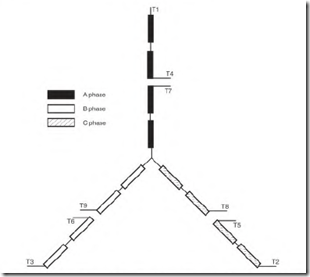
FIGURE 6.1 The four-pole nine-lead motor with two poles in each half of its phase.
each separated into two equal circuits. The end of each phase is connected together, forming a Y connection (Fig. 6.1).
The two circuits of each phase can be externally connected in series or parallel. Series is for high voltage, and parallel is for low voltage. The highvoltage connection (series) is always rated twice as high as the low-voltage connection (parallel).
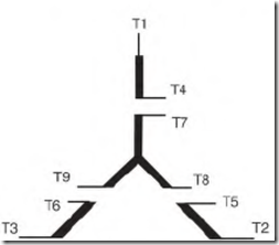
The connection schematic (Fig. 6.2) can be used as a guide for testing any nine-lead wye-connected motor. Identical length between numbers on a schematic means the data are the same, that is, Tl to T4, T2 to T5, T3 to T6, T7 to T8 and to T9. Identical circuits can be comparison-tested, which is an easy, reliable, and accurate method of checking a winding. Identical faults in each identical circuit (six total) are possible, but extremely remote.
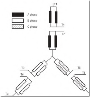
Internally, a winding may have parallel wye circuits (Fig. 6.3). This reduces the winding’s wire size. (Smaller wire is easier to form and insert into the slots.) Motors that are 5 horsepower and larger usually have multiple internal wye connections.
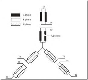
If there is more than one internal wye connection, each half circuit will have one or more parallel circuits. An open circuit in a parallel connection
FIGURE 6.2 Using the nine-lead schematic to do the comparison test.
FIGURE 6.3 A four-pole two- and four-wye nine-lead motor.
(multiwye) will show test results different from those of an open circuit in a one-wye connection (Fig. 6.4).
Lead numbers Tl and T4 are the first half of the phase A circuit. Lead T7 starts the remaining half of the A-phase circuit and ends at the internal wye.
Lead numbers T2 and T5 are the first half of the phase C circuit. Lead T8 starts the remaining half of the C-phase circuit and ends at the internal wye.
Lead numbers T3 and T6 are the first half of the phase B circuit. Lead T9 starts the remaining half of the B-phase circuit and ends at the internal wye.
FIGURE 6.4 A four-pole four-wye nine-lead motor with an open circuit.
Leads Tl and T4, T2 and T5, and T3 and T6 have exactly the same data between them. Leads T7, T8, and T9 have twice as many turns (between them) as the three pairs have.
With the low-voltage (parallel) connection, line 1 connects to Tl and T7; line 2 to T2 and T8; and line 3 to T3 and T9. Leads T4, T5, and T6 are connected together and insulated, forming an external wye (Fig. 6.5). Leads Tl, T2, and T3 have identical data to leads T7, T8, and T9.
With the high-voltage (series) connection, line 1 connects to T l, line 2 to T2, and line 3 to T3. Lead T4 connects to T7, T5 connects to T8, and T6 connects to T9. All are insulated separately (Fig. 6.6).
The motor winding data are the same from line 1 to line 2, line 2 to line 3, and line 3 to line 1.
Current flow from line to line in a wye connection will pass through two complete phases (Fig. 6.7).


