Objectives
After studying this unit, the student will be able to:
• Discuss why mechanical contacts should be spring loaded
• Discuss problems associated with contact bounce
• Describe methods of eliminating contact bounce
• Connect a bounceless switch circuit using digital logic gates
When a control circuit is constructed, it must have sensing devices to tell it what to do. The number and type of sensing devices used are de termined by the circuit. Sensing devices can range from a simple push button to float switches, limit switches, and, pressure switches. Most of these sensing devices use some type of mechanical switch to indicate their condition. A float switch, for example, indicates its condition by opening or closing a set of contacts, figure 62-1. The float switch can “tell” the control circuit that a liquid is either at a certain level or not. Most of the other types of sensing devices use this same method to indicate some condition. A pressure switch indi cates that a pressure is either at a certain level or not, and a limit switch indicates if some device has moved a certain distance or if a device is present or absent from some location.
Almost all of these devices employ a snap action switch. When a mechanical switch is used, the snap action is generally obtained by spring loading the contacts. This snap action is necessary to insure good contact when the switch operates. Assume that a float switch is used to sense when water reaches a certain level in a tank. If the water rises at a slow rate, the contacts will come together at a slow rate, resulting in a poor connection. However, if the contacts are spring loaded, when the water reaches a certain level, the contacts will snap from one position to another.
Although most contacts have a snap action, they do not generally close with a single action. When the movable contacts meet the stationary contact, there is often a fast bouncing action. This means that the contacts may actually make and break contact three or four times in succession be fore the switch remains closed. When this type of switch is used to control a relay, contact bounce does not cause a problem because relays are rela tively slow-acting devices, figure 62-2.
When this type of switch is used with an electronic control system, however, contact bounce can cause a great deal of trouble. Most digital logic circuits are very fast-acting and can count each pulse when a contact bounces. Depending on the specific circuit, each of these pulses may be inter preted as a command. Contact bounce can cause the control circuit to literally “loose its mind”.
Since contact bounce can cause trouble in an electronic control circuit, contacts are debounced before they are permitted to “talk” to the control system. When contacts must be debounced, a cir cuit called a bounceless switch is used. Several cir cuits can be used to construct a bounceless switch, but the most common construction method uses digital logic gates. Although any of the inverting gates can be used to construct a bounceless switch, in this example only two will be used.
Before construction of the circuit begins, the operation of a bounceless switch circuit should first be discussed. The idea is to construct a circuit that will lock its output either high or low when it detects the first pulse from the mechanical switch. If its output is locked in a position, it will ignore any other pulses it receives from the switch. The output of the bounceless switch is connected to the input of the digital control circuit. The control circuit will now receive only one pulse instead of a series of pulses.
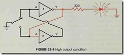
The first gate used to construct a bounceless switch is the INVERTER. The computer symbol and the truth table for the INVERTER are shown in figure 62-3. The bounceless switch circuit using INVERTERS is shown in figure 62-4. The output of the circuit should be high with the switch in the position shown. The switch connects the input of INVERTER # 1 directly to ground, or low. This causes the output of INVERTER #1 to be at a high state. The output of INVERTER #1 is con nected to the input of INVERTER #2. Since the input of INVERTER #2 is high, its output is low. The output of INVERTER #2 is connected to the input of INVERTER #1. This causes a low condition to be maintained at the input of IN VERTER #1.
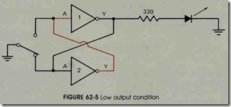
If the position of the switch is changed as shown in figure 62-5, the output will change to low. The switch now connects the input of IN VERTER #2 to ground, or low. The output of INVERTER #2 is, therefore, high. The high out put of INVERTER #2 is connected to the input of INVERTER # 1. Since the input connected to INVERTER # 1 is now high, its output becomes low. The output of INVERTER # 1 is connected to the input of INVERTER #2. This forces a low input to be maintained at INVERTER #2. Notice that the output of one INVERTER is used to lock the input of the other INVERTER.
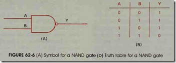
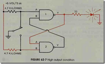
The second logic gate used to construct a bounceless switch is the NAND gate. The com puter symbol and the truth table for the NAND gate are shown in figure 62-6. The circuit in figure 62-7 shows the construction of a bounceless switch using NAND gates. In this circuit, the switch has input A of gate # 1 connected to low, or ground. Since input A is low, the output is high. The out put of gate # 1 is connected to input A of gate #2. Input B of gate #2 is connected to a high through the 4.7 kilohm resistor. Since both inputs of gate #2 are high, its output is low. This low output is connected to input B of gate # 1. Since gate # 1 now has a low connected to input B, its output is forced to remain high even if contact bounce causes a momentary high at input A.
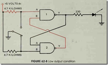
When the switch changes position as shown in figure 62-8, input B of gate #2 is connected to a low. This forces the output of gate #2 to be come high. The high output of gate #2 is con nected to input B of gate # 1. Input A of gate # 1 is connected to a high through a 4.7 kilohm resis tor. Since both inputs of gate # 1 are high, its out put is low. This low is connected to input A of gate #2, which forces its output to remain high even if contact bounce causes a high to be momen tarily connected to input B.
The output of this circuit will remain con stant even if the switch contacts bounce. The switch has now been debounced and is ready to be connected to the input of an electronic control circuit.
REVIEW QUESTIONS
1. Why should mechanical contacts be spring loaded?
2. Name three examples of sensing devices.
3. Why must contacts be debounced before they are connected to electronic control circuits?
4. What function does a bounceless switch circuit perform?
5. Name two types of logic gates that can be used to construct a bounceless switch circuit.


