Effect of Excitation on Armature Current and Power Factor
The value of excitation for which back e.m.f. Eb is equal (in magnitude) to applied voltage V is known as 100% excitation. We will now discuss what happens when motor is either over-excited or under-exicted although we have already touched this point in Art. 38-8.
Consider a synchronous motor in which the mechanical load is constant (and hence output is also constant if losses are neglected).
Fig. 38.47 (a) shows the case for 100% excitation i.e., when Eb = V . The armature current I lags behind V by a small angle f. Its angle q with ER is fixed by stator constants i.e. tan q = X S / Ra.
In Fig. 38.47 (b)* excitation is less than 100% i.e., Eb < V. Here, ER is advanced clockwise and so is armature current (because it lags behind ER by fixed angle q). We note that the magnitude of I is increased but its power factor is decreased (f has increased). Because input as well as V are constant, hence the power component of I i.e., I cos f remains the same as before, but wattless component I sin f is increased. Hence, as excitation is decreased, I will increase but p.f. will decrease so that power component of I i.e., I cos f = OA will remain constant. In fact, the locus of the extremity of current vector would be a straight horizontal line as shown.
Incidentally, it may be noted that when field current is reduced, the motor pull-out torque is also reduced in proportion.
Fig. 38.47 (c) represents the condition for overexcited motor i.e. when Eb > V . Here, the resultant voltage vector ER is pulled anticlockwise and so is I. It is seen that now motor is drawing a leading current. It may also happen for some value of excitation, that I may be in phase with V i.e., p.f. is unity
[Fig. 38.47 (d)]. At that time, the current drawn by the motor would be minimum.
Two important points stand out clearly from the above discussion :
(i) The magnitude of armature current varies with excitation. The current has large value both for low and high values of excitation (though it is lagging for low excitation and leading for higher excitation). In between, it has minimum value corresponding to a certain excitation. The variations of I with excitation are shown in Fig. 38.48 (a) which are known as ‘V ’ curves because of their shape.
(ii) For the same input, armature current varies over a wide range and so causes the power factor also to vary accordingly. When over-excited, motor runs with leading p.f. and with lagging
p.f. when under-excited. In between, the p.f. is unity. The variations of p.f. with excitation
are shown in Fig. 38.48 (b). The curve for p.f. looks like inverted ‘V ’ curve. It would be noted that mini- mum armature current corresponds to unity power factor.
It is seen (and it was pointed out in Art. 38.1) that an over-excited motor can be run with leading power factor. This property of the motor renders it extremely useful for phase advancing (and so power factor correcting) purposes in the case of industrial loads driven by induction motors (Fig. 38.49) and lighting and heating loads supplied through transformers. Both transformers and induction motors draw lagging currents from the line. Especially on light loads, the power drawn by them has a large reactive component and the power factor has a very low value. This reactive component, though essential for operating the electric m a c h i n e entails appreciable loss in many ways. By using synchronous motors in conjunction with induction motors and transformers, the lagging reactive power required by the latter is supplied locally by the leading reactive component taken by the former, thereby relieving the line and generators of much of the reactive component. Hence, they now supply only the active component of the load current. When used in this way, a synchronous motor is called a synchronous capacitor, because it draws, like a capacitor, leading current from the line. Most synchronous capacitors are rated between 20 MVAR and 200 MVAR and many are hydrogen-cooled.
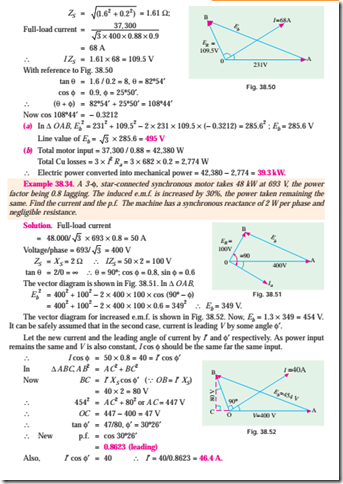
Example 38.33. Describe briefly the effect of vary- ing excitation upon the armature current and p.f. of a synchronous motor when input power to the motor is maintained constant.
A 400-V, 50-Hz, 3-f, 37.3 kW, star-connected synchronous motor has a full-load efficiency of 88%. The synchronous impedance of the motor is (0.2 + j 1.6) W per phase. If the excitation of the motor is adjusted to give a leading p.f. of 0.9, calculate for full-load (a) the induced e.m.f. (b) the total mechanical power developed.


