Semiconductor switching
In this section we shall not be concerned with the switching effect of a single bipolar or field-effect transistor but with the Schmitt trigger and the four- layer semiconductor switching devices such as the thyristor. All of these are electrically-operated switches, and so are not the primary concern of this book, but since their use is so widespread, and so often occurs in conjunction with conventional switches, we must deal with them even if only briefly.
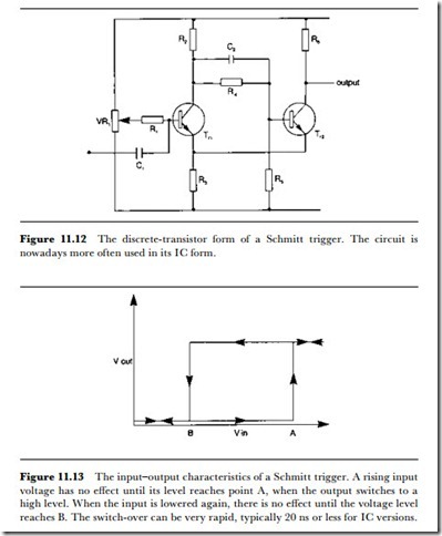
The Schmitt trigger is an old-established switching circuit that has been implemented in turn with thermionic valves, bipolar transistors and field effect transistors. It is still the basis of many switching devices in IC form. A simple version, using bipolar transistors, is illustrated in Figure ll.l2.
The normal circuit bias is arranged so that Tr2 is normally conducting, and the current that is passed through the common emitter resistor R3 is suffi- cient to keep Trl biased off. In many applications the DC voltage of the base of Trl will be ground, but the sensitivity of the circuit can be increased by biasing this base slightly positive. A positive-going signal at the base of Trl will eventually cause this transistor to conduct, and when this happens the fall in voltage at the base of Tr2, along with the drop in current through R3, will make the switch-over very rapid. Vithin a micro- second or so, Trl will be fully conducting and Tr2 shut off. This persists only for as long as the base voltage of Trl causes conduction, however, and when this base voltage reaches a lower level, the rise in collector voltage of
Trl will allow Tr2 to conduct, causing the circuit to snap back to its original state. Once again the change is very rapid, of the order of a )ls in the version illustrated, and is very much faster in TTL IC circuits.
The important feature of the Schmitt trigger, apart from its very fast con- tactless switching, is the difference in voltage levels between switch-on and switch-off. This difference is called voltage hysteresis, and is illustrated in Figure ll.l3, which shows the higher voltage at which the device switches over when an input voltage is rising, and the lower level at which it switches back. The difference between these levels serves to make the
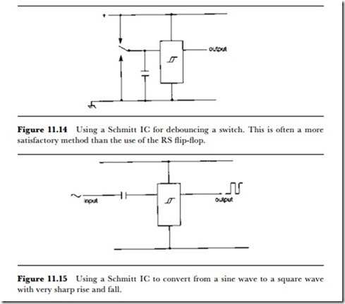
device bounceless, and one common use of the IC form of the Schmitt trigger is to provide debouncing for a mechanical switch, as illustrated in Figure ll.l4. The Schmitt trigger can be used to advantage wherever a slowly changing or analogue voltage has to be used to generate a switch action, usually as part of a digital device. One example is in deriving trigger pulses from sine waves, using a circuit of the type outlined in Figure ll.l5, but a more common application in a true switching application is to generate a switching output from the slowly changing inputs of sensors such as thermistors, Hall-effect devices, liquid level detectors, photocells and similar analogue devices.
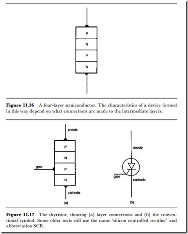
An entirely different class of semiconductor device makes use of a single semiconductor crystal with four separate layers, as shown in Figure ll.l6. The best known device of this class is the thyristor, whose action is very similar to that of the gas-filled thyratron device of earlier years. The thyristor uses connections to only three of the four semiconductor layers, referred to as anode, cathode and gate, respectively (Figure ll.l7). The voltage to be switched is applied between the anode and cathode, with the anode positive with respect to the cathode. Vith the gate at cathode potential, no current will flow between anode and cathode, but when the
gate voltage rises to a given level (usually above 0.6 V) then conduction between anode and cathode is triggered. From then on it will continue until the voltage between anode and cathode falls to a very low value, around 0.2 V.
The gate can be triggered by a pulse, provided that the gate voltage and current are held at triggering level for a sufficient time, around a )ls. The switch-on action is similar to that of a latching type of relay, but there are important differences. First, the power required for switching at the gate is
very low. Second, time is very short compared to that required for a mechanical device (although long compared to other semiconductor switches). Third, the device is unidirectional, i.e., current will not flow unless the anode is positive relative to the cathode. Finally, there is no method of turning off conduction other than reducing the voltage and current between anode and cathode to less than the critical holding level (but see gate turn-off devices, below). Note that the current requirements at the gate call for low-impedance circuits, since gate currents of l00 mA or so may be needed for a brief period.
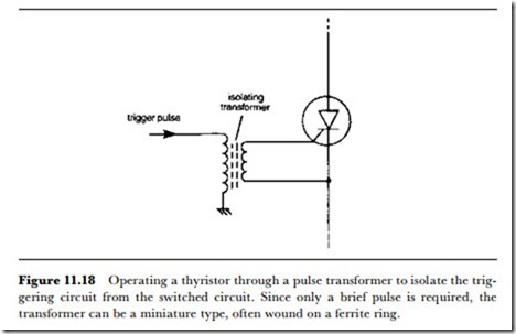
The thyristor is used in relay-type circuits, particularly where the voltage to be switched is AC. This automatically provides for turn-off when the voltage falls to zero in the middle of each cycle, but in DC circuits turn-off can be arranged by shorting the supply briefly with a second thyristor. The thyristor can pass large currents and has the advantage of being contactless, unlike electromagnetic relays, but it has the disadvantage of having no isolation between the gate circuit and the circuit that is being switched. This arises because the gate voltage must be applied between gate and cathode. In many circuits, then, a pulse is fed to the gate-cathode circuit by means of a transformer, which can have very high resistance and breakdown voltage ratings between primary and secondary (Figure ll.l8). Another triggering option is the opto-isolator (see Chapter l0). Some equipment specifications will not, however, accept the use of thyristors in place of electromagnetic relays, particularly in domestic appliances that are subject to high temperatures (such as central heating controllers).
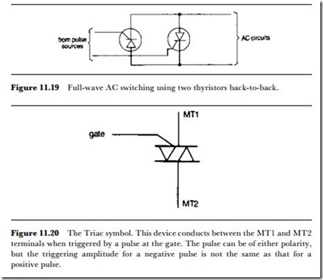
For controlling full wave AC, circuits that use two thyristors connected anode to cathode (Figure ll.l9) can be used, but a more common solution
involves the use of a bi-directional device known as a Triac (the name is a trade mark), as shown in Figure ll.20. The electrodes of the Triac are labelled as MTl, MT2 and gate, with the voltage to be switched applied between MTl and MT2 in either polarity. Triggering is also bi-directional for a swing of about 2 V between the gate and MTl, although the triggering current required depends on the polarity of the triggering signal. Like the thyristor, the Triac is switched off when the voltage and current between MTI and MT2 are at a very low level.
There is one thyristor-like device that can be turned off electrically, known as the gate turn-off (GTO) thyristor or switch. Typically, a device of this type will permit conduction between anode and cathode for a positive pulse of specified voltage, current and duration, and will turn off with a negative pulse of larger voltage but shorter duration. Other devices of the four-layer type include the silicon-controlled switch (SCS), a device in which a lead is taken to each of the four semiconductor layers. This allows the SCS to be used in two modes, either as a form of uni-junction transistor or as a thyristor.
