Eight-Step Switching (Half Stepping)
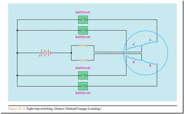
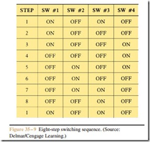
Figure 35 – 8 illustrates the connections for an eight- stepping sequence. In this arrangement, the center tap leads for phases A and B are connected through their own separate current limiting resistors back to the negative of the power supply. This circuit contains four separate single pole switches instead of two switches. The advantage of this arrangement is that each step causes the motor to rotate one-eighth of a tooth instead of one-fourth of a tooth. The motor now requires 400 steps to produce one revolution, which produces an angular rotation of 0.9 degree per step. This results in better stepping resolution, and greater speed capability. The chart in Figure 35–9 illustrates the switch position for each step. Figure 35–10 depicts a solid-state switching circuit for an eight-step switching arrangement. A stepping motor is shown in Figure 35–11.
AC Operation
Stepping motors can be operated on AC voltage. In this mode of operation, they become two-phase AC synchronous constant speed motors and are classified as a permanent magnet induction motor. Refer to the exploded diagram of a stepping motor in Figure 35 – 12. Notice that this motor has no brushes, slip rings, commutator, gears, or belts. Bearings maintain a constant air gap between the permanent magnet rotor and the stator windings. A typical eight-stator pole stepping motor will have a synchronous speed of 72 rpm when connected to a 60 hertz two-phase AC power line.
A resistive-capacitive network can be used to pro- vide the 90 degree phase shift needed to change single- phase AC into two-phase AC. A simple forward-off- reverse switch can be added to provide directional
control. A sample circuit of this type is shown in Figure 35–13. The correct values of resistance and capacitance are necessary for proper operation. Incorrect values can result in random direction of rotation when the motor is started, change of direction when the load is varied, erratic and unstable operation, as well as failure of the motor to start. The correct values of resistance and capacitance will be different with different stepping motors. The manufacturer’s recommendations should be followed for the particular type of stepping motor used.

