By IM steady-state we mean constant speed and load. For a machine fed from a sinusoidal voltage symmetrical power grid, the phase voltages at IM terminals are
![]() Va,b,c = V 2 cos⋅ ω −1t (i−1)⋅ 23π ; i =1,2,3 (13.39)
Va,b,c = V 2 cos⋅ ω −1t (i−1)⋅ 23π ; i =1,2,3 (13.39)
The voltage space phasor Vsb in random coordinates (from (13.27)) is
For steady-state, the current in the space phasor model follows the voltage frequency: (ω1 – ωb). Steady-state in the state space equations means replacing d/dt with j(ω1 – ωb).
Using this observation makes Equations (13.30) become
Vs0 = R is s0 + ω Ψj 1 s0; Ψs0 = L isl s0 + Ψm0;
 Ψr0 = L irl r0 + Ψm0; im0 = is0 +ir0 (13.44)
![]() = R ir r0 + jSω Ψ1 r0; S = (ω −ω1ωr r ); Ψm0 = L im m0 Vr0
= R ir r0 + jSω Ψ1 r0; S = (ω −ω1ωr r ); Ψm0 = L im m0 Vr0
So the form of space phasor model voltage equations under the steady-state is the same irrespective of the speed of the reference system ωb.
When ωb, only the frequency changes of voltages, currents, flux linkages in the space phasor model varies as it is ω1 – ωb.
No wonder this is so, as only Equations (13.44) exhibit the total emf, which should be independent of reference system speed ωb. S is the slip, a variable well known by now. Notice that for ωb = ω1 (synchronous coordinates), d/dt = (ω1 – ωb) = 0. Consequently, for synchronous coordinates the steady-state means d.c. variables.
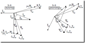
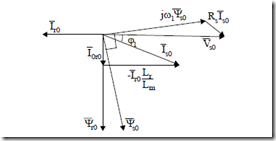
The space phasor diagram of (13.44) is shown in Figure 13.2 for a cage rotor IM.
cage rotor
Figure 13.2 Space phasor diagram for steady-state
From the stator space Equations (13.44) the torque (13.31) becomes
![]() Te = 23 p1 jΨr0 r0i* = 32 P1Ψr0 r0i (13.45) Also, from (13.44),
Te = 23 p1 jΨr0 r0i* = 32 P1Ψr0 r0i (13.45) Also, from (13.44),
Rr With (13.46), alternatively, the torque is
Te = 3 p1 Ψr02 Sω1 (13.47)
2 Rr
Solving for Ψr0 in Equations (13.44) lead to the standard torque formula.
3p1 Vs2 RSr
Te ≈ ω1 Rs +C1 RSr 2 +ω12 (Lls +C L1 lr )2 ; C1 = +1 LLmls (13.48)
Expression (13.47) shows that, for constant rotor flux space-phasor amplitude, the torque varies linearly with speed as it does in a separately excited d.c. motor. So all steady-state performance may be calculated using the spacephasor model as well.
EQUIVALENT CIRCUITS FOR DRIVES
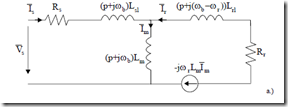
Equations (13.30) lead to a general equivalent circuit good for transients, especially in variable speed drives (Figure 13.3).
![]()
![]()
![]() Vs = R is s +(p+ ωj b )L isls +(p+ ω Ψj b ) m (13.49)
Vs = R is s +(p+ ωj b )L isls +(p+ ω Ψj b ) m (13.49)
Vr = R ir r +(p+ j(ω −ωb r ))L irl r +(p+ j(ω −ωb r ))Ψm
The reference system speed ωb may be random, but three particular values have met with rather wide acceptance.
• Stator coordinates: ωb = 0; for steady-state: p Æ jω1
• Rotor coordinates: ωb = ωr; for steady-state: p Æ jSω1
• Synchronous coordinates: ωb = ω1; for steady-state: p Æ 0
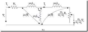
Figure 13.3 The general equivalent circuit a.) and for steady-state b.) (continued)
Also, for steady-state in variable speed drives, the steady-state circuit, the same for all values of ωb, comes from Figure 13.3a with p Æ j(ω1 – ωb) and Figure 13.3b.
Figure 13.3b shows, in fact, the standard T equivalent circuit of IM for steady-state, but in space phasors and not in phase phasors.
A general method to “arrange” the leakage inductances Lsl and Lrl in various positions in the equivalent circuit consists of a change of variables.
![]()
![]() iar = i /a; r Ψma = aLmis +iar (13.50)
iar = i /a; r Ψma = aLmis +iar (13.50)
Making use of this change of variables in (13.49) yields
![]()
![]()
![]() aVr = a R i2Vsr =ar +R i(sps++j((ω −ωp b+ ωj br)()) (La aLs −aLrl −mL)ims )+iar(p++ ω Ψ(pj+ bj()ω −ωbam r ))Ψam (13.51)
aVr = a R i2Vsr =ar +R i(sps++j((ω −ωp b+ ωj br)()) (La aLs −aLrl −mL)ims )+iar(p++ ω Ψ(pj+ bj()ω −ωbam r ))Ψam (13.51)
An equivalent circuit may be developed based on (13.51), Figure 13.4. The generalized equivalent circuit in Figure 13.4 warrants the following comments:
• For a = 1, the general equivalent circuit of Figure 13.4 is reobtained and
• For a = Lm/Lr the inductance term in the “rotor section” “disappears”, being moved to the primary section and
![]()
![]()
![]() aΨam = LLmr Lmis +ir LLmr = LLmr Ψr (13.52)
aΨam = LLmr Lmis +ir LLmr = LLmr Ψr (13.52)
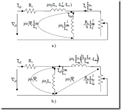
Figure 13.6 Steady-state equivalent circuits
a.) rotor flux oriented b.) stator flux oriented
• For a = Ls/Lm, the leakage inductance term is lumped into the “rotor section” and
![]()
![]()
![]() aΨam = LLs Lm is +ir LLms = Ψs (13.53)
aΨam = LLs Lm is +ir LLms = Ψs (13.53)
m
• This type of equivalent circuit is adequate for stator flux orientation control
• For d.c. braking, the stator is fed with d.c. The method is used for variable speed drives. The model for this regime is obtained from Figure 13.4 by using a d.c. current source, ωb = 0 (stator coordinates, Vr = 0, a = Lm/Lr) The result is shown in Figure 13.5.
For steady-state, the equivalent circuits for ar = Lm/Lr and ar = Ls/Lm and Vr=0 are shown in Figure 13.6.
Example 13.1. The constant rotor flux torque/speed curve.
Let us consider an induction motor with a single rotor cage and constant parameters: Rs = Rr = 1 Ω, Lsl = Lrl = 5 mH, Lm = 200 mH, Ψr0’ = 1 Wb, S = 0.2, ω1 = 2π6 rad/s, p1 = 2, Vr = 0. Find the torque, rotor current, stator current, stator and main flux and voltage for this situation. Draw the corresponding space phasor diagram.
Solution
We are going to use the equivalent circuit in Figure 13.6a and the rotor current and torque expressions (13.46 and 13.47):
Te = 3 p1 Ψr02 Sω =1 3 21![]() 2 0.2 2 6⋅ π = 22.608Nm
2 0.2 2 6⋅ π = 22.608Nm
2 Rr 2 1
Ψr0 = −0.2 2 6⋅ π 1 = −7.536A
Ir0 = − ωS 1
Rr 1
![]() The rotor current is placed along real axis in the negative direction. The rotor flux magnetization current Ir0 (Figure 13.6a) is
The rotor current is placed along real axis in the negative direction. The rotor flux magnetization current Ir0 (Figure 13.6a) is
![]() I0r0 = −j(−Ir0 )LRSr2LLmr = −j(−SωIr01L)Rm r = −j0.2 2 6 0.2
I0r0 = −j(−Ir0 )LRSr2LLmr = −j(−SωIr01L)Rm r = −j0.2 2 6 0.2![]() j5A
j5A
ω1 Lmr
The stator current
![]()
![]() Is0 = −Ir0 Lr + I0r0 = 7.536 0.205 − j5 = 7.7244− j5.0A
Is0 = −Ir0 Lr + I0r0 = 7.536 0.205 − j5 = 7.7244− j5.0A
Lm 0.2
![]() Ψs0 = L Is s0 + L Im r0 = 0.205(7.7244− j5.0)+0.2(−7.536)= 0.076− j1.025 The airgap flux Ψm is
Ψs0 = L Is s0 + L Im r0 = 0.205(7.7244− j5.0)+0.2(−7.536)= 0.076− j1.025 The airgap flux Ψm is
![]() Ψm0 = Lm (Is0 + Ir0 )= 0.2 7.( 7244− j5.0−7.536)= 0.03768− j1.0
Ψm0 = Lm (Is0 + Ir0 )= 0.2 7.( 7244− j5.0−7.536)= 0.03768− j1.0
The rotor flux is
Ψr0 = Ψm0 + L Irl r0 = 0.03768− j1.0+0.005(−7.536)= −j1.0 (as expected)
The voltage Vso is:
![]() Vs0 = ω Ψj 1 s0 + R Is s0 = j2 6 0.π ( 076− j1.025)+1 7.( 7244− j5.0)= 46.346− j2.136 The corresponding space phasor diagram is shown in Figure A.
Vs0 = ω Ψj 1 s0 + R Is s0 = j2 6 0.π ( 076− j1.025)+1 7.( 7244− j5.0)= 46.346− j2.136 The corresponding space phasor diagram is shown in Figure A.
