State Variables
As was mentioned in the introduction, state variables are not unique and they can be defined in various forms. It will be shown in the proceeding chapters and it is better to define the state variables right from the beginning when the governing differential equations for various elements of a control system is derived.
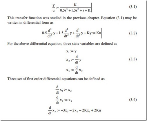
One possible method is to define state variables from the transfer function. The number of state variables must be equal to the order of the transfer function. Some books show the derivative with respect to time by a dot above variable, that is, (x“) . For clarity, the derivative with respect to time will be shown by the standard symbol of d/dt .
Without loss of generality, a simple third order transfer function with numerator as constant value is considered:
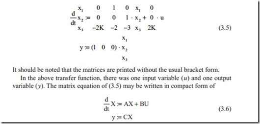
It can be seen that by defining three state variables, the transfer function is converted to three first order differential equations. Various methods can now be used to solve the above set of first order differential equations. The above process can be repeated for any transfer function regardless of its order. The number of state variables equals the order of the transfer function. The above set of equation can be written in matrix form as
It should be noted that the matrices are printed without the usual bracket form.
In the above transfer function, there was one input variable ( u) and one output variable ( y). The matrix equation of (3.5) may be written in compact form of
In the above equation, X is the vector containing n state variables and its dimension is n × 1. A is called the system matrix and its dimension is n × n. B is called the input matrix and its dimension is n × m, where m is the number of input variables. In the above example, there was only one input variable. In servo control systems, there are generally two input variables, one is the command signal and the other one is external torque or force applied to the system. The second equation is the output equation where Y is the output variables and its dimension is l × 1 and C is the output matrix and its dimension is l × n. In servo control systems, there is generally one output variable of output position.
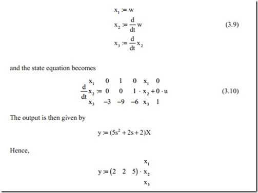
If the numerator of the transfer function is a polynomial in s, then the transforma- tion of the transfer function to state equation is slightly different. Without loss of generality, the procedure will be explained with one example. Consider the following transfer function,
Transfer function (3.8) is similar to the previous example and we can define three state variables as
It can be seen that in this case, all state variables contribute to the output. Although the above form of equations were derived from the transfer function, the state variables as will be shown in the proceeding chapter, can be defined from the governing differential equation for each element.
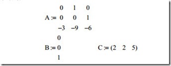
In the above example, the system matrix A, the input vector B, and output vector, C are as follows:
When the system matrix A, the input matrix B, and the output matrix C are defined, the dynamic behavior of the system can completely be studied. In some applications, although very rare in servo control systems, there might be direct contribution from the input vector U to the output vector Y. In this case, another term should be added to the output equation.


