Objectives
After studying this unit, the student will be able to:
• Describe the operation of a start-stop relay control circuit
• Describe the operation of the basic gates used in this unit
• Describe the operation of the solid-state control circuit
• Discuss practical wiring techniques for connecting digital logic circuits
• Connect a start-stop, push-button control using logic gates
In this unit a digital circuit will be designed to perform the same function as a common relay circuit. The relay circuit is a basic stop-start, push-button circuit with overload protection, fig ure 63-1.
Before beginning the design of an electronic circuit that will perform the same function as this relay circuit, the operation of the relay circuit should first be discussed. In the circuit shown in figure 63-1, no current can flow to relay coil M because the normally open start button and the normally open contact are controlled by relay coil M.
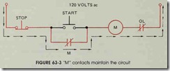
When the start button is pushed, current flows through the relay coil and normally closed overload contact to the power source, figure 63-2 . When current flows through relay coil M, the con tacts connected parallel to the start button close. These contacts maintain the circuit to coil M when the start button releases and returns to its open position, figure 63-3.
The circuit will continue to operate until the stop button is pushed and breaks the circuit to the coil, figure 63-4. When the current flow to the coil stops, the relay de-energizes and contact M re opens. Since the start button is now open and contact M is open, there is no complete circuit to the relay coil when the stop button is returned to its normally closed position. If the relay is to be re started, the start button must be pushed again to provide a complete circuit to the relay coil.
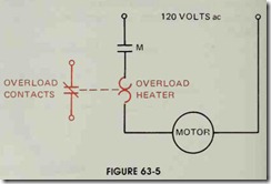
The only other logic condition that can occur in this circuit is caused by the motor connected to the load contacts of relay M. The motor is con nected in series with the heater of an overload re lay, figure 63-5. When coil M energizes, it closes the load contact M as shown in figure 63-6. When the load contact closes, it connects the motor to the 120-volt, ac power line.
If the motor is overloaded, it will cause too much current to flow through the circuit. When a current greater than normal flows through the overload heater, the heater produces more heat than it does under normal conditions. If the cur rent becomes high enough, it will cause the nor mally closed overload contact to open. Notice that the overload contact is electrically isolated from the heater. The contact, therefore, can be con nected to a different voltage source than the motor.
If the overload contact opens, the control circuit is broken and the relay de-energizes as if the stop button had been pushed. After the overload contact has been reset to its normally closed posi tion, the coil will remain de-energized until the start button is again pressed.
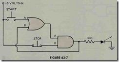
Now that the logic of the circuit is under stood a digital logic circuit that will operate in this manner can be designed. The first problem is to find a circuit that can be turned on with one push button and turned off with another. The circuit shown in figure 63-7 can perform this function. This circuit consists of an OR gate and an AND gate. Input A of the OR gate is connected to a normally open push button which is connected to + 5 volts de. Input B of the OR gate is connected to the output of the AND gate. The output of the OR gate is connected to input A of the AND gate. Input B of the AND gate is connected through a normally closed push button to + 5 volts de. This normally closed push button is used as the stop button. The output of the AND gate is the output of the circuit.
To understand the logic of this circuit, as sume that the output of the AND gate is low. This produces a low at input B of the OR gate. Since the push button connected to input A is open, a low is produced at this input also. When all inputs of an OR gate are low, its output is also low. The low output of the OR gate is connected to input A of the AND gate. Input B of the AND gate is connected to a high through the normally closed push-button switch. Since input A of the AND gate is low, the output of the AND gate is forced to remain in a low state.
When the start button is pushed, a high is connected to input A of the OR gate. This causes the output of the OR gate to change to high. This high output is connected to input A of the AND gate. The AND gate now has both of its inputs high, so its output changes from a low to a high state. When the ouput of the AND gate changes to a high state, input B of the OR gate becomes high also. Since the OR gate now has a high con nected to its B input, its output will remain high when the push button is returned to its open con dition and input A becomes low. Notice that this circuit operates the same as the relay circuit when the start button is pushed. The output changes from a low state to a high state and the circuit locks in this condition so the start button can be reopened.
When the normally closed stop button is pushed, input B of the AND gate changes from high to low. When input B changes to a low state, the output of the AND gate changes to a low state also. This causes a low to appear at input B of the OR gate. The OR gate now has both of its inputs low, so its output changes from a high state to a low state. Since input A of the AND gate is now low, the output is forced to remain low when the stop button returns to its closed position and input B becomes high. The circuit designed here can be turned on with the start button and turned off with the stop button.
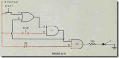
The next design task is to connect the over load contact to the circuit. The overload contact must be connected in such a manner that it will cause the output of the circuit to turn off if it opens. One’s first impulse might be to connect the overload contact to the circuit as shown in figure 63-8. In this circuit, the output of AND gate # 1 has been connected to input A of AND gate #2. Input B of AND gate #2 has been connected to a high through the normally closed overload con tact. If the overload contact remains closed, input B will remain high. The output of AND gate #2 is, therefore, controlled by input A. If the output of AND gate # 1 changes to a high state, the out put of AND gate #2 will also change to a high state. If the output of AND gate #1 becomes low, the output of AND gate #2 will become low also.
If the output of AND gate #2 is high and the overload contact opens, input B will become low and the output will change from a high to a low state. This circuit appears to operate with the same logic as the relay circuit until the logic is ex amined closely. Assume that the overload contacts are closed and the output of AND gate # 1 is high. Since both inputs of AND gate #2 are high, the output is also high. Now assume that the over load contact opens and causes input B to change to a low condition. This forces the output of AND gate #2 to change to a low state also. Input A of AND gate #2 is still high, however. If the over load contact is reset, the output will immediately change back to a high state. If the overload con tact opens and is then reset in the relay circuit, the relay will not restart itself. The start button must be pushed to restart the circuit. Although this is a small difference in circuit logic, it could become a safety hazard in some cases.
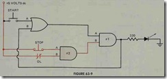
This fault can be corrected with a slight de sign change. Refer to figure 63-9. In this circuit, the normally closed stop button has been con nected to input A of AND gate #2, and the nor mally closed overload switch has been connected to input B. As long as both of these inputs are high, the output of AND gate #2 will provide a high to input B of AND gate # 1. If either the stop button or the overload contact opens, the out put of AND gate #2 will change to a low state. When input B of AND gate #2 changes to a low state, it will cause the output of AND gate # 1 to change to a low state and unlock the circuit, just as pushing the stop button did in the circuit shown in figure 63-8. The logic of this digital cir cuit is now the same as the relay circuit.
Although the logic of this circuit is now cor rect, there are still some problems that must be corrected. When gates are used, their inputs must be connected to a definite high or low. When the start button is in its normal position, input A of the OR gate is not connected to anything. When an input is left in this condition, the gate may not be able to determine if the input should be high or low. The gate could, therefore, assume either condition. To prevent this, inputs must always be connected to a definite high or low.
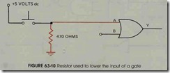
When using TTL logic, inputs are always pulled high with a resistor as opposed to being pulled low. If a resistor is used to pull an input low as shown in figure 63-10, it will cause the gate to have a voltage drop at its output. This means that in the high state, the output of the gate may be only 3 or 4 volts instead of 5 volts. If this out put is used as the input of another gate, and the other gate has been pulled low with a resistor, the output of the second gate may be only 2 or 3 volts. Notice that each time a gate is pulled low through a resistor, its output voltage becomes low. If this were done through several steps, the output volt age would soon become so low it could not be used to drive the input of another gate.
Figure 63-11 shows a resistor used to pull the input of a gate high. In this circuit, the push but ton is used to connect the input of the gate to ground, or low.
The push button can be adapted to produce a high at the input instead of a low by adding an INVERTER as shown in figure 63-12. In this cir cuit, a pull-up resistor is connected to the input of an INVERTER. Since the input of the IN VERTER is high, its output will produce a low at input A of the OR gate. When the normally open push button is pressed, a low will be produced at the input of the INVERTER. When the input of the INVERTER becomes low, its output becomes high. Notice that the push button will now pro duce a high at input A of the OR gate when it is pushed.
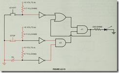
Since both of the push buttons and the nor mally closed overload contact are used to provide high inputs, the circuit is changed as shown in fig ure 63-13. Notice that the normally closed push button and the normally closed overload switch connected to the inputs of AND gate #2 are con nected to ground instead of Vcc. When the switches are connected to ground, a low is pro vided to the input of the INVERTERS to which they are connected. The INVERTERS, therefore, produce a high at the input of the AND gate. If one of these normally closed switches opens, a high will be provided to the input of the IN VERTER. This will cause the output of the IN VERTER to become low. If the logic of the circuit shown in figure 63-13 is checked, it can be seen that it is the same as the logic of circuit 63-9.
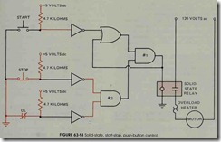
The final design problem for this circuit concerns the output. So far, a light-emitting diode has been used as the load. The LED is used to indicate when the output is high and when it is low. The original circuit, however, was used to control a 120-volt ac motor. This control can be accom plished by connecting a solid-state relay to the output in place of the LED, figure 63-14. In this circuit, the output of AND gate # 1 is connected to the input of an opto-isolated, solid-state relay. When the output of the AND gate changes to a high condition, the solid-state relay turns on and connects the 120-volt ac load to the line.
REVIEW QUESTIONS
1. In a relay circuit, what function is served by the holding contacts?
2. What is the function of the overload relay in a motor control circuit?
3. What conditions of input must exist if an OR gate is to produce a high output?
4. What conditions of input must exist if an AND gate is to produce a high output?
5. When connecting TTL logic, why are inputs pulled high instead of low?
6. Referring to figure 63-9, how would this circuit operate if input B of the OR
gate was reconnected to input A of AND gate # 1 instead of its output?
7. Referring to figure 63-12, what function does the INVERTER serve in this circuit?


