Until the advent of solid-state drives, induction motors were not used in many applications requiring speed control. The normal operating range of an induction motor is within less than 5 percent slip. At larger slip, the efficiency of the motor will drop significantly because the rotor copper losses are directly proportional to the slip of the motor (PRCL sPAG). The speed of an induction motor can be controlled by varying the synchronous speed or the slip for a given load. The synchronous speed can be varied by changing the electrical frequency or the number of poles. The slip can be changed by varying the rotor resistance or terminal voltage.
 SPEED CONTROL BY CHANGING THE LINE FREQUENCY
The rate of rotation of the stator magnetic field depends on the electrical frequency. The no- load point on the torque-speed curve changes with the frequency (Fig. 7.1). The base speed is the synchronous speed at rated conditions.
The speed of the motor can be adjusted by using variable frequency control. A variable frequency induction motor drive can control the speed from 5 percent of the base load to twice the base speed.
There are limits on the voltage and torque as the frequency is varied to ensure safe operation. When the speed is being reduced below the base speed, the terminal voltage to the stator should be decreased linearly with decreasing stator frequency. This process is called derating. If the motor is not derated, the steel in the core will saturate and large magnetization current will flow in the machine.
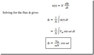
The flux in the core of an induction motor is given by Faraday’s law:
If the electrical frequency decreases by 10 percent while the voltage remains constant, the flux in the core will increase by 10 percent. The magnetization current will also increase by 10 percent in the unsaturated region of the motor’s magnetization curve. The magneti- zation current will increase by much more than 10 percent in the saturated region.
Since induction motors are designed to operate near saturation, the increase in flux due to the decrease in frequency will cause a large magnetization current to flow. The stator
the maximum power rating must decrease linearly with decreasing voltage to protect the stator from overheating.
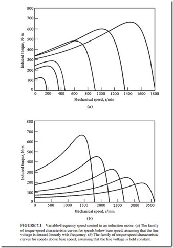
Figure 7.1a illustrates a family of torque-speed characteristic curves for speeds below the base speed. The stator voltage was assumed to vary linearly with frequency.
When the frequency applied to the motor exceeds the rated frequency, the stator volt- age is held constant at the rated value. Although the applied voltage can be raised above the rated value without reaching saturation, it is limited to the rated voltage. This is done to pro- tect the winding insulation of the motor. As the frequency increases while the voltage remains constant, the resulting flux and the maximum torque will decrease with it.
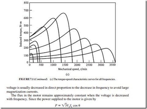
Figure 7.1b shows a family of torque-speed characteristic curves for speeds higher than the base speed, assuming that the stator voltage is held constant. Figure 7.1c shows a family of torque-speed characteristic curves for speeds higher and lower than the base speed, assuming that the stator voltage is varied linearly with frequency below base speed and is held constant at rated value above base speed (the rated speed for the motor shown in Fig. 7.1 is 1800 r/min). Changing the line frequency with solid-state motor drives has become the preferred method for induction motor speed control.


