Factors Controlling Motor Speed
It has been shown earlier that the speed of a motor is given by the relation
It is obvious that the speed can be controlled by varying (i) flux/pole, F (Flux Control)
(ii) resistance Ra of armature circuit (Rheostatic Control) and (iii) applied voltage V (Voltage Con- trol). These methods as applied to shunt, compound and series motors will be discussed below.
Speed Control of Shunt motors
(i) Variation of Flux or Flux Control Method
It is seen from above that N µ 1/F. By decreasing the flux, the speed can be increased and vice versa. Hence, the name flux or field control method. The flux of a d.c. motor can be changed by changing Ish with help of a shunt field rheostat (Fig. 30.1). Since Ish is relatively small, shunt field rheostat has to carry only a small
V current, which means I2R loss is small, so that rheostat is small in size. This method is, therefore, very efficient. In non-interpolar machine, the speed can be increased by this method in the ratio 2 : 1. Any further weakening of flux F adversely affects the communication and hence puts a limit to the maximum speed obtainable with the method. In machines fitted with interpoles, a ratio of maximum to minimum speed of 6 : 1 is fairly common.
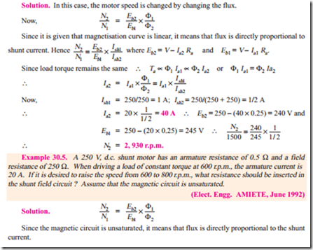
Example 30.1. A 500 V shunt motor runs at its normal speed of 250 r.p.m. when the armature current is 200 A. The resistance of armature is 0.12 ohm. Calculate the speed when a resistance is inserted in the field reducing the shunt field to 80% of normal value and the armature current is 100 ampere. (Elect. Engg. A.M.A.E. S.I. June 1992)
to be added to the field circuit to increase speed to 1000 r.p.m. at an armature current of 80 A. Assume flux proportional to field current. Armature resistance = 0.15 W and field winding resistance = 250 W. (Elect. Technology, Hyderabad Univ. 1991)
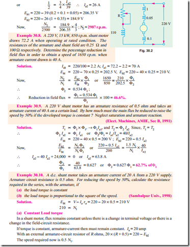
Example 30.7. A 220-V, 10-kW, 2500 r.p.m. shunt motor draws 41 A when operating at rated conditions. The resistances of the armature, compensating winding, interpole winding and shunt field winding are respectively 0.2 W, 0.05 W, 0.1 W and 110 W. Calculate the steady-state values of armature current and motor speed if pole flux is reduced by 25%, a 1 W resistance is placed in series with the armature and the load torque is reduced by 50%.
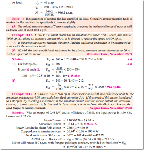
Example 30.11. A 250 V shunt motor runs at 1000 r.p.m. at no-load and takes 8 A. The total armature and shunt field resistances are respectively 0.2 ohm, 250 ohm. Calculate the speed when loaded and taking 50 A. Assume the flux to be constant.
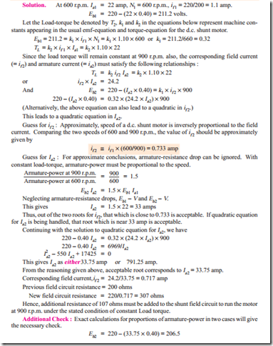
There are two simplifying assumptions in this case, which must be stated before further calculations :
1. Load-torque is constant,
2. No Load Losses are constant.
(These statements can be different which leads to variations in the next steps of calculations.)
For constant load-torque, the condition of constant flux per pole results into constant armature current, which is 36.64 A.
With an armature current of 36.64 A, let the external resistance required for this purpose be R.
36.64 R = 217.1 – 108.5 = 108.6 V, R = 2.964 ohms
Total Losses
[In place of if 2, Ia2 can be evaluated first. Its guess-work will give Ia2 @ 1.5 ´ 20 @ 30 amp]
Continuing with the solution of the equation to evaluate a value of if 2, accepting that value which is near 0.73 amp, we have if 2 = 0.71865. [Note that other value of if 2, which is 0.04235, is not acceptable.]. Corresponding Ia2 = 30.6 amp. Previous shunt field current, if 1 = 1.1, Rf 1 = 200 W. New shunt field current, if 2 = 0.71865, Rf 2 = 220/0.71865 = 306 W. Final answer is that a resistor of 106 ohms is to be added to the field circuit to run the motor at 900 r.p.m. at constant torque.
Example 30.16. A 220 V d.c. shunt motor has an armature resistance of 0.40 ohm and field- resistance of 200 ohms. It takes an armature current of 22 A and runs at 600 r.p.m. It drives a load whose torque is constant. Suggest a suitable method to raise the speed to 900 r.p.m. Calculate the value of the controllable parameter. (Nagpur Univ., April 1998)
Tutorial Problems 30.1
1. A d.c. shunt motor runs at 900 r.p.m. from a 460 V supply when taking an armature current of 25 A. Calculate the speed at which it will run from a 230-V supply when taking an armature current of 15 A. The resistance of the armature circuit is 0.8 W. Assume the flux per pole at 230 V to have decreased to 75% of its value at 460 V. [595 r.p.m.]
2. A 250 V shunt motor has an armature resistance of 0.5 W and runs at 1200 r.p.m. when the armature current is 80 A. If the torque remains unchanged, find the speed and armature current when the field is strengthened by 25%. [998 r.p.m. ; 64 A]
3. When on normal full-load, a 500 V, d.c. shunt motor runs at 800 r.p.m. and takes an armature current 42 A. The flux per pole is reduced to 75% of its normal value by suitably increasing the field circuit resistance. Calculate the speed of the motor if the total torque exerted on the armature is (a) unchanged (b) reduced by 20%.
The armature resistance is 0.6 W and the total voltage loss at the brushes is 2 V.
[(a) 1,042 r.p.m. (b) 1,061 r.p.m.]
4. The following data apply to d.c. shunt motor.
Supply voltage = 460 V ; armature current = 28 A ; speed = 1000 r.p.m. ; armature resistance = 0.72 W. Calculate (i) the armature current and (ii) the speed when the flux per pole is increased to 120% of the initial value, given that the total torque developed by the armature is unchanged.
[(i) 23.33 A (ii) 840 r.p.m.]
5. A 100-V shunt motor, with a field resistance of 50 W and armature resistance of 0.5 W runs at a speed of 1,000 r.p.m. and takes a current of 10 A from the supply. If the total resistance of the field circuit is reduced to three quarters of its original value, find the new speed and the current taken from the supply. Assume that flux is directly proportional to field current. [1,089 r.p.m. ; 8.33 A]
6. A 250 V d.c. shunt motor has armature circuit resistance of 0.5 W and a field circuit resistance of 125 W. It drives a load at 1000 r.p.m. and takes 30 A. The field circuit resistance is then slowly increased to 150 W. If the flux and field current can be assumed to be proportional and if the load torque remains constant, calculate the final speed and armature current. [1186 r.p.m. 33.6 A]
7. A 250 V, shunt motor with an armature resistance of 0.5 W and a shunt field resistance of 250 W drives a load the torque of which remains constant. The motor draws from the supply a line current of 21 A when the speed is 600 r.p.m. If the speed is to be raised to 800 r.p.m., what change must be affected in the shunt field resistance ? Assume that the magnetization curve of the motor is a straight line. [88 W]
8. A 240 V, d.c. shunt motor runs at 800 r.p.m. with no extra resistance in the field or armature circuit, on no-load. Determine the resistance to be placed in series with the field so that the motor may run at 950 r.p.m. when taking an armature current of 20 A. Field resistance = 160 W. Armature resistance = 0.4 W. It may be assumed that flux per pole is proportional to field current. [33.6 W]
9. A shunt-wound motor has a field resistance of 400 W and an armature resistance of 0.1 W and runs off 240 V supply. The armature current is 60 A and the motor speed is 900 r.p.m.; Assuming a straight line magnetization curve, calculate (a) the additional resistance in the field to increase the speed to 1000 r.p.m. for the same armature current and (b) the speed with the original field current of 200 A. [(a) 44.4 W (b) 842.5 r.p.m.]
10. A 230 V d.c. shunt motor has an armature resistance of 0.5 W and a field resistance of 76 2/ W. The motor draws a line current of 13 A while running light at 1000 r.p.m. At a certain load, the field circuit resistance is increased by 38 1/ W. What is the new speed of the motor if the line current at this load is 42 A ? [1400 r.p.m.] (Electrical Engg. ; Grad I.E.T.E. Dec. 1986)
11. A 250 V d.c. shunt motor runs at 1000 r.p.m. and takes an armature current of 25 amp. Its armature resistance is 0.40 ohm. Calculate the speed with increased load with the armature current of 50 amp. Assume that the increased load results into flux-weakening by 3%, with respect to the flux in previous loading condition. (Nagpur Univ., April 1996)
(ii) Armature or Rheostatic Control Method
This method is used when speeds below the no-load speed are required. As the supply voltage is normally constant, the voltage across the armature is varied by inserting a variable rheostat or resistance (called controller resistance) in series with the armature circuit as shown in Fig. 30.4 (a). As controller resistance is increased, p.d. across the armature is decreased, thereby decreasing the armature speed. For a load constant torque, speed is approximately proportional to the p.d. across the armature. From the speed/armature current characteristic [Fig. 30.4 (b)], it is seen that greater the resistance in the armature circuit, greater is the fall in the speed.
It may be noted that brush voltage drop has not been considered.
Example 30.19. A 500 V d.c. shunt motor has armature and field resistances of 1.2 W and 500 W respectively. When running on no-load, the current taken is 4 A and the speed is 1000 r.p.m. Calculate the speed when motor is fully loaded and the total current drawn from the supply is 26 A. Estimate the speed at this load if (a) a resistance of 2.3 W is connected in series with the armature and (b) the shunt field current is reduced by 15%. (Electrical Engg. I, Sd. Patel Univ. 1985)
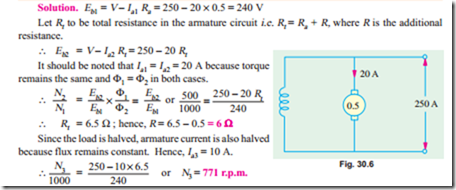
Example 30.20. A 250-V shunt motor (Fig. 30.6) has an armature current of 20 A when running at 1000 r.p.m. against full load torque. The armature resistance is 0.5 W. What resistance must be inserted in series with the armature to reduce the speed to 500 r.p.m. at the same torque and what will be the speed if the load torque is halved with this resistance in the circuit ? Assume the flux to remain constant throughout and neglect brush contact drop.
(Elect. Machines AMIE Sec. B Summer 1991)
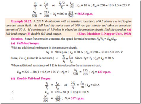
Example 30.21. A 250-V shunt motor with armature resistance of 0.5 ohm runs at 600 r.p.m. on full-load and takes an armature current of 20 A. If resistance of 1.0 ohm is placed in the armature circuit, find the speed at (i) full-load torque (ii) half full-load torque.
(Electrical Machines-II, Punjab Univ. May 1991)
Example 30.23. The speed of a 50 h.p (37.3 kW) series motor working on 500 V supply is 750 at full-load and 90 per cent efficiency. If the load torque is made 350 N-m and a 5 ohm resistance is connected in series with the machine, calculate the speed at which the machine will run. Assume the magnetic circuit to be unsaturated and the armature and field resistance to be 0.5 ohm. (Electrical Machinery I, Madras Univ. 1986)
Example 30.25. A 240 V shunt motor has an armature current of 15 A when running at 800 r.p.m. against F.L. torque. The arm. resistance is 0.6 ohms. What resistance must be inserted in series with the armature to reduce the speed to 400 r.p.m., at the same torque ?
What will be the speed if the load torque is halved with this resistance in the circuit ? Assume the flux to remain constant throughout. (Elect. Machines-I Nagpur Univ. 1993)
Example 30.26. (a) A 400 V shunt connected d.c. motor takes a total current of 3.5 A on no load and 59.5 A at full load. The field circuit resistance is 267 ohms and the armature circuit resistance is 0.2 ohms (excluding brushes where the drop may be taken as 2 V). If the armature reaction effect at ‘full-load’ weakens the flux per pole by 2 percentage change in speed from no-load to full-load.
(b) What resistant must be placed in series with the armature in the machine of (a) if the full- load speed is to be reduced by 50 per cent with the gross torque remaining constant ? Assume no change in the flux. (Electrical Machines, AMIE Sec. B, 1989)
Example 30.27. A d.c. shunt drives a centrifugal pump whose torque varies as the square of the speed. The motor is fed from a 200 V supply and takes 50 A when running at 1000 r.p.m. What resistance must be inserted in the armature circuit in order to reduce the speed to 800 r.p.m. ? The armature and field resistance of the motor are 0.1 W and 100 W respectively.
(Elect. Machines, Allahabad Univ. 1992)
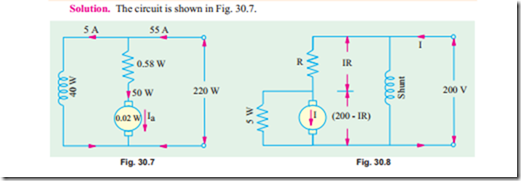
Example 30.29. A 200 V shunt motor with a shunt resistance of 40 W and armature resistance of 0.02 W takes a current of 55 A and runs at 595 r.p.m. when there is a resistance of 0.58 W in series with armature. Torque remaining the same, what change should be made in the armature circuit resistance to raise the speed to 630 r.p.m. ? Also find
(i) At what speed will the motor run if the load torque is reduced such that armature current is 15 A.
(ii) Now, suppose that a divertor of resistance 5 W is connected across the armature and series resistance is so adjusted that motor speed is again 595 r.p.m., when armature current is 50 A. What is the value of this series resistance ? Also, find the speed when motor current falls of 15 A again.
The effect of armature divertor is obvious. The speed without divertor is 668.5 r.p.m. and with armature divertor, it is 637 r.p.m.
(iii) Voltage Control Method
(a) Multiple Voltage Control
In this method, the shunt field of the motor is connected permanently to a fixed exciting voltage, but the armature is supplied with different voltages by connecting it across one of the several different voltages by means of suitable switchgear. The armature speed will be approximately proportional to these different voltages. The intermediate speeds can be obtained by adjusting the shunt field regulator. The method is not much used, however.
(b) Ward-Leonard System
This system is used where an unusually wide (upto 10 : 1) and very sensitive speed control is required as for colliery winders, electric excavators, elevators and the main drives in steel mills and blooming and paper mills. The arrangement is illustrated in Fig. 30.9.
M1 is the main motor whose speed control is required. The field of this motor is permanently connected across the d.c. supply lines. By applying a variable voltage across its armature, any desired speed can be obtained. This variable voltage is supplied by a motor-generator set which consists of either a d.c. or an a.c. motor M2 directly coupled to generator G.
The motor M2 runs at an approximately constant speed. The output voltage of G is directly fed to the main motor M1. The voltage of the generator can be varied from zero up to its maximum value by means of its field regulator. By reversing the direction of the field current of G by means of the reversing switch RS, generated voltage can be reversed and hence the direction of rotation of M1. It should be remembered that motor generator set always runs in the same direction.
Despite the fact that capital outlay involved in this system is high because (i) a large output machine must be used for the motor generator set and (ii) that two extra machines are employed, still it is used extensively for elevators, hoist control and for main drive in steel mills where motor of ratings 750 kW to 3750 kW are required. The reason for this is that the almost unlimited speed control in either direction of rotation can be achieved entirely by field control of the generator and the resultant economies in steel production outwiegh the extra expenditure on the motor generator set.
A modification of the Ward-Leonard system is known as Ward-Leonard-Ilgner system which uses a smaller motor-generator set with the addition of a flywheel whose function is to reduce fluctuations in the power demand from the supply circuit. When main motor M1 becomes suddenly over- loaded, the driving motor M2 of the motor generator set slows down, thus allowing the inertia of the flywheel to supply a part of the overload. However, when the load is suddenly thrown off the main motor M1, then M2 speeds up, thereby again storing energy in the flywheel.
When the Ilgner system is driven by means of an a.c. motor (whether induction or synchronous) another refinement in the form of a ‘slip regulator’ can be usefully employed, thus giving an additional control.
The chief disadvantage of this system is its low overall efficiency especially at light loads. But as said earlier, it has the outstanding merit of giving wide speed control from maximum in one direction through zero to the maximum in the opposite direction and of giving a smooth acceleration.
If O.C.C. is plotted from the above given data, then it would be found that the excitation required to give 343.77 V is 2.42 A.
Generator exciting current = 2.42 A


