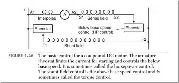
The motor’s nameplate shows the base speed of the motor. Figure 1.46 shows a basic compound motor control. Controls can range from hand-cranked rheostats to electronic circuitry. Regardless of their complexity, they will control the components of the motor as illustrated in Fig. 1.46.
Armature Control for Starting and for Below Base Speed
Full voltage should be applied to the shunt field when the armature control is used. Full voltage to the shunt field will give the motor constant torque (from zero to base speed). The armature control allows enough amperes through the armature to give it breakaway torque. The resistance is lowered gradually as the motor starts to accelerate. The motor accelerates to the RPM required by the load. Full voltage is applied to the armature at base speed.
Shunt Field Control for Starting and for Above Base Speed
The shunt field control (Fig. 1.46) applies full voltage to the shunt field when the motor starts. The motor accelerates until the RPM is stabilized at base speed. At this RPM the lines of force furnished by the shunt field are at maximum. The amperes flowing in the armature are limited by countervoltage to a value needed for the load and the motor’s internal losses.
The shunt field control (sometimes called above base speed, field weakening, or torque control) can now be used. It adds resistance to the shunt field, lowering the amperes. This will reduce the shunt field’s magnetic lines of force or flux. Less magnetism from the shunt field lowers the counter-voltage and allows more amperes to flow in the armature. The result is a higher base speed. The torque is reduced, but increased RPM gives the motor constant horsepower above base speed.
All controls have a field loss feature that shuts the motor off if the shunt field circuit opens. If the shunt field disconnects or opens while the motor is running with no load, the armature will accelerate until it is destroyed. If the motor is loaded and can’t accelerate, the armature will burn out. Without the magnetism of the shunt field, the armature develops very little countervoltage. Only the resistance of the armature windings limits the amperes.
The control components used to control the shunt field are small because of the small number of amperes the shunt field requires.
The shunt field can be excited separately with a different power source. With separate excitation, the shunt field’s supply voltage isn’t affected by the high amperes of the armature circuit.
The Differential Connection (Motor)
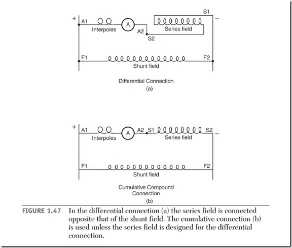
The connection for the compound motor (described earlier) has the series field connected so that its polarity is the same as that of the shunt field. This connection is called cumulative. It adds the magnetic flux (lines of force) of the series field to that of the shunt field, enabling the motor to maintain stable RPM as the load changes.
When the series field polarity is opposite that of the shunt field, the connection is called differential. With the differential connection (Fig. 1.47), the series field has an effect that is opposite that of the cumulative connection (instead of adding to the shunt field magnetism, the series field reduces it).
As the load increases, the series field amperes increase. If connected to the opposite polarity as the shunt field, the series field’s flux (lines of
force) cancels an equal amount of shunt field flux. This reduces the lines of force being cut by the armature conductors, lowering the counter-voltage.
Lower counter-voltage allows the amperes through the armature to increase. Higher armature amperes will accelerate the motor to a higher speed. Higher speed increases the counter-voltage, lowering amperes in the armature and series field circuit.
The (fully energized) shunt field flux quickly brings the armature speed back down. When the load demand again slows the armature, the cycle starts again. The result is wide swings in speed.
Armature Components
• Commutator
• Commutator film
• Armature windings
• Equalizer shunts
• Laminated iron
Commutator
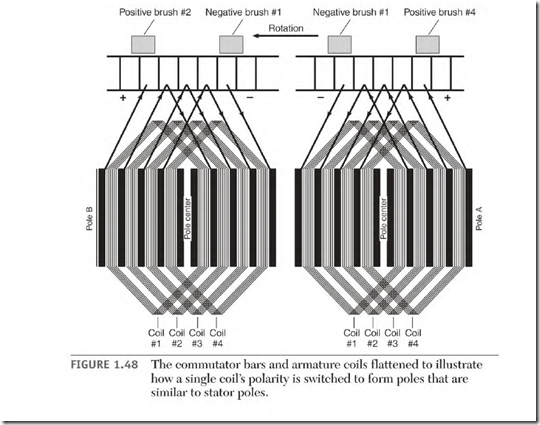
The commutator is made of copper segments that are separated and insulated with mica. The commutator segments function as one side of a switch, and the brushes function as the other. Together they control the direction of the current flow (similar to a diode). The commutator’s function is to control the polarity of the coils connected to its segments.
As the armature turns, two commutator segments (and the coil attached to them) have current flow in one direction. The coil is now part of pole A (Fig. 1.48). When the coil’s segments go under a brush, they short together, causing line current to stop flowing in the coil.
When the coil’s segments come out from under the brush, the current is reversed, and the coil is now part of pole B—the opposite polarity pole in
Positive brush #2 Negative brush #1 Negative brush #1 Positive brush #4
the direction of rotation. No matter how fast the armature turns, the poles in its iron will remain in the same position (relative to the stator poles). The commutator and brushes are high-maintenance components because of friction and electrical wear. (Electrical wear is caused by constant switching.)
Commutator Film
Good film is a very important part of the commutator function. It conducts current and provides lubrication between the brushes and the copper segments. The film shouldn’t be removed unless the commutator is reworked.
It takes from several hours to several days to reestablish the film. During this time, the brushes and the commutator are wearing excessively.
The film has some resistance, and removing it will increase the voltage output of a generator and increase the speed of a motor. Slightly better performance, however, isn’t worth the amount of increased wear to both brushes and commutator.
The film is roughly 1/1000 the thickness of a human hair. Elements of the film include carbon, graphite, copper oxide, and water vapor. Carbon, graphite, and copper oxide are current-conducting elements of the film. Water vapor and graphite provide lubrication. The brushes and commutator need a good balance of these elements for maximum life.
Lack of oxygen lowers the copper oxide element of the film, reducing its current-carrying ability. This occurs in totally enclosed and explosion-proof machines.
Dry weather reduces the water vapor content of the film, resulting in increased wear.
There is no “best color” for the film, and it can vary from machine to machine. The color can vary from tan to black and still do a good job.
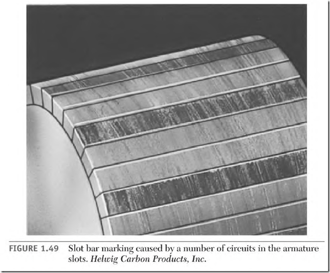
A color difference in several adjacent bars (Fig. 1.49), with this pattern repeated all around the commutator, doesn’t indicate a problem. It means there is more than one circuit (or coil) per slot. As the armature rotates, the circuits in this slot are commutated at a slightly different position (relative to the field poles). If the bars commutate in different positions, each bar commutates a different current value. (This causes each bar to have a different color.)
The color pattern should be the same around the commutator. A difference in the color pattern may indicate a problem.
If there is bar etching, it can be reduced by moving the brush holder slightly less than one segment. Move the brush holder against rotation if it’s a motor and with rotation if it’s a generator.
Armature Windings
Armature windings are made with large wire. Most of the amperes flow through the armature in a motor. All of the output amperes flow through the armature in a generator.
Lap and wave are the two basic connections for the armature windings. The lap connection has as many brushes as there are poles. The wave connection has half as many brushes as there are poles.
Whatever the connection, the poles are precisely spaced and balanced magnetically. Most windings have the same number of turns per slot. If they don’t, the total turns per pole will be the same. This fact makes it possible to use the comparison test when troubleshooting.
Equalizer Shunts
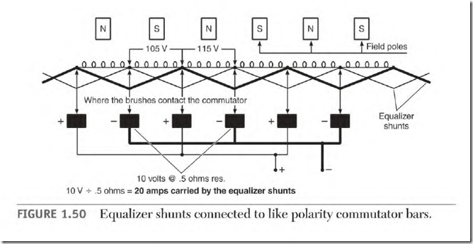
Equalizer shunts (back connections) are used to balance the effects of voltage unbalance in the armature windings, They are placed in the commutator’s wire slots or risers. They join segments located under like pole brushes.
Unbalanced voltage will occur between a brush and its two adjacent brushes (Fig. 1.50). The resulting current will flow in the equalizer shunt wire instead of the brushes and commutator. At full load, the commutator is already carrying its rated amperes.
Without equalizer shunts, the amperes caused by unbalanced voltage adds to the full-load amperes. The resulting commutator damage is the same as if some of the commutator bars were overloaded. High current in these bars will cause them to discolor and erode. Bar erosion will eventually cause a flat spot on the commutator.
Laminated Iron
Laminated iron is the magnetic path for the armature. The laminations are thin because of a high-frequency magnetic polarity change in the iron teeth. The teeth in a high-speed DC armature will have a polarity change well over 100 cycles per second.
A thin coat of insulation separates the laminations. If the laminations are shorted together, eddy current is generated. This current will develop a hot spot in the laminations that will damage the adjacent slot insulation.
Repair centers always core test and, if necessary, re-insulate the laminations before rewinding an armature.
FIGURE 1.50 Equalizer shunts connected to like polarity commutator bars.
