Audio to electrical sensors and transducers
The sound to electrical energy transducer is the microphone, and microphone types are classified by the type of electrical transducer they use. In addition to the transducer, however, a microphone will use acoustic filters, passages whose shape and dimensions modify the response of the overall system. These are needed because each transducer will have its own response that is determined by resonances in the materials as well as by the transducing principle itself. The correction to a more uniform response has to be made by means of the acoustic passages in the microphone housing. This type of compensation is preferable to the use of electrical methods, because acoustic filters can have much sharper effects with less impact on the rest of the frequency range.
• Microphones are used as sensors in sound-level meters. This calls for a microphone whose frequency response is carefully controlled, with electronic compensation for any substantial peaks or dips. The reading is usually in terms of decibels above the threshoLd noise LeveL, i.e., the sound pressure level at which the ear can just detect that a sound is present.
The characteristics of a microphone are both acoustic and electrical. The overall sensitivity is expressed as mV or J.V of electrical output per unit intensity of sound wave or in terms of the acceleration produced by the sound wave. In addition, though, the impedance of the microphone is of con- siderable importance. A microphone with high impedance usually has a fairly high electrical output, but the high impedance makes it very suscepti- ble to hum pick-up, either magnetically or electrostatically coupled. A low impedance value is usually associated with very low output, but hum pick- up is almost negligible.
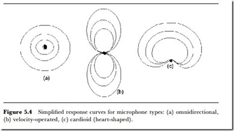
Another factor of importance is whether the microphone is directional or omni-directional. If the operating principle of the microphone is the sensing of the pressure of the sound wave, then the microphone will be
omni-directionaL, picking up sound arriving from any direction. If the micro- phone responds to the velocity (speed and direction) of the sound wave, then it is a directionaL microphone, and the sensitivity has to be measured in terms of direction as well as amplitude of sound wave. The microphone types (see Figure 5.4) are known as pressure or velocity operated, omnidirectional, or some form of directional response (such as cardioid).
The type of transducer does not necessarily determine the operating principle as velocity or pressure, because the acoustic construction of the microphone is usually a more important factor. If, for example, the micro- phone uses a sealed capsule construction, then the pressure of the sound wave will be the factor that determines the response. If the microphone uses a diaphragm or other moving element that is exposed to the sound wave on all sides, then the system will be velocity operated.
THE CARBON MICROPHONE
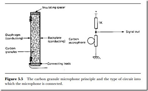
The carbon granule type of microphone was the first type to be developed for telephone use, and was still in use for telephones long after it had been abandoned for any other purposes. It has now been replaced by the electret capacitor type (see later) even for telephone use. The principle is illustrated in Figure 5.5, and uses loosely packed granules of carbon held between a diaphragm and a backplate. When the granules are compressed, the resistance between diaphragm and backplate drops considerably, and the vibration of the diaphragm can therefore be converted into variations of resistance of the granules. The microphone does not, therefore, generate a voltage and requires an external supply before it can be used.
The sole advantage of the carbon granule microphone is that it provides
an output that is colossal by microphone standards, with outputs of 1 V peak-to-peak possible. The linearity is very poor, the structure causes multiple resonances in the audio range, and the resistance of the granules alters in a random way even with no sound present, causing a high noise level. The predominance of the carbon microphone in the early days of telephony was due to its high output at a time when no amplification was possible, and the introduction of valve and, later, transistor amplifiers, caused the rapid demise of the carbon microphone for serious audio use.
THE MOVING IRON (VARIABLE RELUCTANCE) MICROPHONE
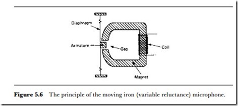
This type of microphone uses a powerful magnet that contains a soft-iron armature in its magnetic circuit, with the armature attached to a diaphragm. The principle is illustrated in Figure 5.6. The magnetic reluctance of the circuit alters as the armature moves, and this in turn alters the total magnetic flux in the magnetic circuit. A useful comparison is of a battery connected in series with a fixed and a variable resistor chain. A coil wound around the magnetic circuit at any point will give an EMF which is proportional to each change of magnetic flux. This makes the electrical wave from the microphone 90o out of phase with the sound wave amplitude, and proportional to the acceleration of the diaphragm. Most moving iron microphones are manufactured in the form of sealed capsules or with very limited access to one side of the diaphragm, so that the pressure of the sound wave is the predominant quantity that determines the action.
The linearity of the conversion can be reasonable for small amplitudes of movement of the armature, but is very poor for large amplitudes. The linearity can be considerably improved by appropriate shaping of the armature and careful attention to its path of vibration. These features depend on the maintenance of close tolerances in the course of manufacturing the microphones, so that there will inevitably be differences in linearity between samples of microphones of this type from the same production line. The maximum useable output level from a moving iron microphone can be high, of the order of 50 mV, and the output impedance is also high, typically several hundred ohms. Because the flux path in the transducer is almost closed, external changes in the magnetic field will be very efficiently picked up, and the result is that the magnetic component of mains hum is superimposed on the output. This can be reduced by shielding the magnetic circuit, using mu-metal or similar alloys. The magnetic circuit that is the predominant feature of this type of microphone also makes the instrument heavier than some other types.
MOVING COIL MICROPHONE
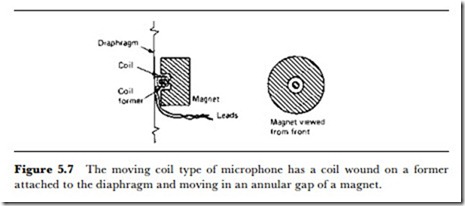
The moving coil microphone uses a constant-flux magnetic circuit in which the electrical output is generated by moving a small coil of wire in the magnetic circuit (Figure 5.7). The coil is attached to a diaphragm, and the whole arrangement is usually in capsule form, making this pressure- operated rather than velocity-operated. As before, the maximum output occurs as the coil reaches maximum velocity between the peaks of the sound wave so that the electrical output is at 90o phase angle to the sound wave.
The coil is usually small, and its range of movement very small, so that linearity is excellent for this type of microphone. The coil has a low impedance, and the output is correspondingly low, but not so low that it has to compete with the noise level of an amplifier. The low inductance of
the coil makes it much less susceptible to hum pick-up from the magnetic field of the mains wiring, and it is possible to use hum-compensating (non- moving) coils, known as humbuckers, in the structure of the microphone to reduce hum further by adding an antiphase hum signal to the output of the main coil.
RIBBON MICROPHONE
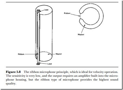
The ribbon microphone is the logical conclusion of the moving coil principle, in which the coil has been reduced to a strip of conducting ribbon (Figure 5.8), with the signal being taken from the ends of the
ribbon. An intense magnetic field is used, so that the movement of the ribbon cuts across the maximum possible magnetic flux to generate an electrical output whose peak value is as usual at 90o phase to the sound wave.
One of several features that make the ribbon microphone unique is the fact that it is a velocity-operated microphone, because the ribbon is affected by the velocity of the air in the sound wave rather than its pressure. This type of microphone is therefore used in situations where directional response is important, such as a voice commentary in noisy sur- roundings. The linearity is excellent, and the ribbon microphone is predominantly used where high quality reproduction is of paramount importance.
The construction of the ribbon microphone inevitably makes the output extremely low, and the microphones are usually equipped with a transfor- mer to raise both the signal voltage level and the impedance level. The hum pick-up is also extremely low, and advantage can be taken of this to use a balanced output transformer to minimize hum pick-up in the micro- phone leads (Figure 5.9).
To be effective, a ribbon microphone has to be constructed to very precise limits, and good ribbon microphones are very expensive items, costing more than most domestic hi-f iusers would contemplate spending on a complete sound system. The directional qualities are ideally suited to stereo broadcasting, although for some purposes the very directional response can be undesirable, and moving coil units have to be used.
PIEZOELECTRIC MICROPHONES
The piezoelectric transducer has the advantage over all the other types mentioned in this chapter of not being confined to use in air. A piezoelectric transducer can be bonded to a solid or immersed in a non-conducting liquid so as to pick up sound signals in any of these carriers. In addition, the piezoelectric transducer can be used easily at ultrasonic frequencies, with some types being capable of use in the high MHz region. All piezoelec- tric transducers require a crystalline material in which the ions of the crystal are displaced in an asymmetrical way when the crystal is strained.
The linearity can vary considerably with the type of material that is used, and from sample to sample.
The original types of crystal microphones used Rochelle salt crystal coupled to a diaphragm. This ensured very high output levels (of the order of 100 mV), with very high output impedance and very poor linearity. Rochelle salt was not used for long because of its unfortunate habit of changing to an inactive form when kept at a moderately high temperature and humidity. Many pioneer users of tape recorders were puzzled to find that their microphones (and gramophone pick-ups) refused to work after the machine was brought down from the loft or up from the cellar after a hot summer.
The types of piezoelectric transducers that are used nowadays are mostly synthetic rather than natural crystals. One such material is barium titanate, which is used in piezoelectric transducers for frequencies up to several hundred kHz. The original type of piezoelectric microphone which used a diaphragm coupled to the crystal is seldom seen nowadays. The sensitivity of modern piezoelectric materials to vibration is such that the impact of the sound wave on the crystal alone is enough to provide an adequate output. Most microphones of this type are made as pressure- operated types because one side of the crystal is normally used for securing the assembly to its casing.
The piezoelectric microphone has a very high impedance level and a much higher output than other types. The impedance level is of the order of several megohms, as distinct from a few ohms for a moving coil type. At this very high impedance level, electrostatic pick-up of hum is almost impossible to avoid, along with the problems of the loading and filtering effect of the microphone cable. For low-quality microphones, of the type that were once supplied with tape or cassette recorders, this is of little importance, but it rules out the use of a simple type of piezoelectric micro- phone for studio purposes. For such purposes, the crystal transducer can be coupled directly to a MOS preamplifier that can provide a low-impedance output at the same high voltage level as is provided by the piezoelectric transducer. The preamplifier operating voltage can be supplied from a built-in battery to avoid the problems of running supply cables along with signal cables.
CAPACITORMICROPHONES
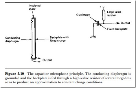
The capacitor microphone is a remarkable example of a principle that was comparatively neglected until another, equally old, idea was harnessed along with it. The outline of a capacitor microphone is illustrated in Figure 5.10. The amount of electric charge between two surfaces is fixed, and one of the surfaces is a diaphragm that can be vibrated by a sound wave. The vibration causes a variation of capacitance that, because of the fixed
charge, causes a voltage wave. The output impedance is very high, and the amount of output depends on the normal spacing between the plates – the smaller this spacing, the greater the output for a given amplitude of sound wave. The construction of the microphone ensures that it is always pressure-operated.
The two main objections to the capacitor microphone in the past were the need for a high-voltage supply and the hum pick-up problems of the very high impedance. The high-voltage supply (called a polarizing voltage) was needed to provide the fixed charge; this was done by connecting the supply voltage to one plate through a very large value resistor. The high impedance made it difficult to use the microphone with more than a short length of cable (which added to the ‘dead’ capacitance), although it was suited to the valve input stages of the time.
The capacitor microphone can be very linear in operation and can provide very good quality audio signals without the need for elaborate con- structional techniques. This was realized by a few users, notably Grundig, who always provided capacitor microphones with their tape recorders in the early days of domestic tape recording. There were also a few manufac- turers who specialized in high-quality capacitor microphones for studio use, but capacitor microphones were always a rarity in comparison with moving iron and moving coil types.
The revival of the capacitor microphone came about as a result of a revival of interest in an old idea, the eLectret. An electret is the electrostatic equivalent of a magnet, a piece of insulating material that is permanently charged. The principle, which has been known for a century, states that if a hot plastic material (in the broadest sense of a material that can easily be
softened by heating) is subject to a strong electric field as it hardens, it will retain a charge for as long as it remains solid. Materials such as acrylics (like Perspex) are electrets, and the idea was once considered for the manufacture of monoscope tubes, i.e., tubes that provide a TV test signal.
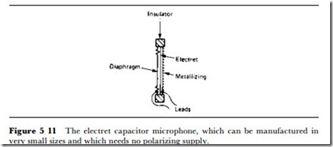
A slab of electret, however, is the perfect base for a capacitor microphone, providing the fixed charge that is required without the need for a polarizing voltage supply. This allows the very simple construction of a capacitor microphone, consisting only of a slab of electret metallized on the back, a metal (or metallized plastic) diaphragm, and a spacer ring (Figure 5.11), with the connections taken to the conducting surface of the diaphragm and of the electret. This is now the type of microphone that is built into cassette recorders, and even in its simplest and cheapest versions is of considerably better audio quality than the piezoelectric types that it displaced.
The high impedance of the capacitor electret microphone is no handicap now that MOS preamplifiers can be used, and for studio quality capacitor microphones the preamplifier can be battery operated so as to avoid the need for supply lines. The linearity of the microphone is independent of the electret, provided that the electret can supply a truly fixed charge. If the electret becomes leaky, as is possible through surface contamination, then the low-frequency response of the microphone will be degraded.
Another form of capacitor microphone uses a light film of pyroelectric material (see Chapter 4) whose polarization (separation of charge) is also changed by strain. Using such a film, metallized on one side, as one plate of a capacitor whose other plate is a perforated metal sheet creates a simple microphone whose output can be larger than that of most other capacitor types.
MICROPHONE PROBLEMS
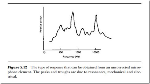
Each specific type of microphone has its own problems and advantages, but
there are problems that are common to all microphone types. The main problem of this kind is resonance, which will cause the output from the microphone to be distorted at some frequency, to form either a peak or a trough (Figure 5.12). These resonances can be electrical, but are much more likely to be mechanical and, as such, more difficult to deal with.
The two main techniques for dealing with mechanical resonances are shifting and damping. A resonance can be shifted by altering the mass of the resonating part, so that the resonance occurs outside the audio region. Reducing the vibrating mass will have the effect of shifting the resonance to a higher frequency, and when this technique is used, the aim is usually to shift the resonance to 30 kHz or higher. When the resonance is (unusually) at a low audio frequency, then adding mass can shift it to a lower, sub-audio frequency – this is more often a loudspeaker problem than a microphone problem.
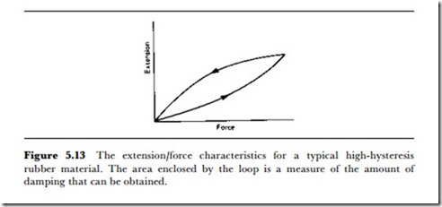
Damping a resonance means that the energy of the resonating material must be dissipated, and this has to be done by using yielding materials rather then elastic materials like metals. Synthetic rubber materials can be made which have very high mechanical hysteresis (Figure 5.13). These make excellent damping materials to support diaphragms and other vibrating parts, and in general the use of damping calls for a considerable knowledge of materials of this type. Damping alone is seldom a cure for a bad resonance, and design effort has to be directed both to frequency- shifting the resonance and to damping it.
FREQUENCY AND WAVELENGTH
The use of microphones allows the frequency of sound waves to be measured
by connecting either an oscilloscope or a frequency meter to the micro- phone. It is more usual now to have a combined microphone and frequency meter. The wavelength of sound waves in air can be calculated from the frequency, using the relation:
where ). is wavelength in metres, c is the speed of sound in air, and f is the measured frequency of the sound waves. Since the frequency of a sound wave can be measured very precisely, this is used in preference to direct measurements of wavelength. If the sound wave is being propagated in another medium, the value for speed of sound in that medium can be used in the equation.
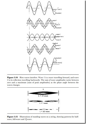
Direct methods of measuring wavelength depend on setting up standing waves by reflecting a sound wave. When a wave is reflected, the forward wave and the reflected wave (Figure 5.14) can add to give wavepeaks (antinodes) and wave minima (nodes). If the reflecting surface is an integral number of half-wavelengths away, standing waves are set up with the nodes and antinodes in fixed positions (Figure 5.15).
The distance between two adjacent nodes is half of the wavelength, as is the distance between two adjacent antinodes. By measuring the distance between nodes (or between antinodes) we can find the wavelength directly, but such measurements can never be as precise as the calculation of wave- length from frequency.
• A microphone can distort the amplitude of the wave, in the sense of not providing a perfectly linear amplitude response, but it has no such effect on frequency.
• Hydrophones are a specialized form of microphone used under water, normally using piezoelectric transducers.
• Building acoustics are discussed in Chapter 7.
