Ten points of servicing
Start with the symptoms provided by the electronic product. In a TV chassis, use the symptomsfound on the TV screen and speaker. An insufficient vertical raster indicates trouble in the vertical section. Pulled width might be caused by the low-voltage power supply, horizontal circuits, or pincushion circuits. Intermittent sound might be caused by a defective audio IC.
Start with the symptoms , and isolate the defective component. Break the circuits down, and list the probable circuits where the defective part may be located. Then make voltage, resistance, and solid-state tests in those circuits to locate the defective part.
Ten points of servicing
Start with the symptoms provided by the electronic product. In a TV chassis, use the symptoms found on the TV screen and speaker. An insufficient vertical raster indicates trouble in the vertical section. Pulled width might be caused by the low-voltage power supply, horizontal circuits, or pincushion circuits. Intermittent sound might be caused by a defective audio IC.
Start with the symptoms, and isolate the defective component. Break the circuits down, and list the probable circuits where the defective part may be located. Then make voltage, resistance, and solid-state tests in those circuits to locate the defective part.
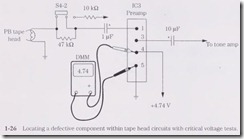
To locate the defective section, you must know where each section is located on the chassis without the help of a schematic. For instance, if a tape player has weak and distorted sound, with normal AM and FM stereo reception, the audio frequency (AF) and audio output circuits are normal. The defective component must be between the tape head and the stereo function switch. The most obvious things to check are a dirty tape head, electrolytic coupling capacitors, preamp transistors or ICs, and the supply voltage to the tape head circuits (Fig. 1-26).
Locate all large components on the chassis to find the defective circuits. Around large filter capacitors are the low-voltage power supply components. Look at the large transistors or IC audio output components for defective sound circuits. Vertical circuits are nearby when locating the vertical output transistors. The horizontal output transistors and regulators might be found on a large separate or chassis heat sink. Try to locate large parts in each section that point to the correct symptom.
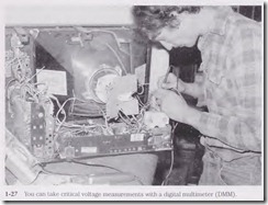
After locating the defective circuits, take voltage and resistance measurements. Some technicians check solid-state parts first. The most accurate instrument for taking voltage and resistance measurements within a solid-state chassis is the digital multi meter (DMM) (Fig. 1-27). Voltage and resistance measurements of less than 1 V or 1 ohm are required within the solid-state chassis. Accurate base bias voltages (0.3 to 0.6 V) be tween base and emitter terminals indicate not only if the transistor is good but also if it is a germanium or silicon type.
Next, scope waveforms are needed to signal trace the various circuits. When the horizontal output circuits are functioning, the horizontal waveform can be traced fron1 the vertical oscillator, amp, and output to the vertical yoke winding. Low distortion can be found in the stereo circuits with a sine or square wave at the input. Scope the audio stages for clipping and distortion.
After several tests, the defective part must be removed from the circuit. Desoldering equipment and solid mesh or wick material can be used to remove excess solder. Be careful when removing transistor pins so as not to pull or pop off thin PC board wiring coru1ections. Too much heat might dislodge or destroy small PC board wiring. The con trolled electronic soldering system or station is ideal for removing and replacing PC board-mounted components.
Check the suspected part after it is removed from the chassis. Sometimes the intermittent transistor may be normal after heat is applied and it is removed from the circuit. Replace it. Transistor, continuity, resistance, and special equipment tests may indicate a defective part after removal.
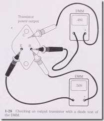
Test the new component before installing. Check transistors, capacitors, resistors, choke coils, diodes, and zener diodes before installation (Fig. 1-28). Make sure the parts are properly installed before soldering. By checking the part before installation, you may save a lot of valuable service time and confusion.
Install the new part with careful soldering of the terminals. Too much solder can overlap between terminals and short out the component when the chassis is turned on. Too much heat may damage a semiconductor. Clean out all solder and rosin flux between terminals.
Double-check all terminals. Are they all placed on the correct PC board wiring? Remember, the transistor or IC component can be soldered with reversed terminals. Check the wiring connections . Make sure that no cold joints or inter connected connections are made. Check and double-check before turning on the chassis.
The following steps must be taken to locate, isolate, repair, and replace a defective component:
1. Check the symptoms.
2. Isolate the circuits.
3. Locate the part.
4. Take voltage and resistance tests.
5. Perform scope tests.
6. Remove the defective part.
7. Check the defective part.
8. Test the new part.
9. Install the new part.
10. Clean up and double-check.
Safety measures
Excessive lightning or power outage damage can destroy a TV set, VCR, receiver, or cassette player. Extensive dan1age to the low-voltage circuits and tuner in a TV can total the entire chassis. when the 220-V neutral wire breaks before entering the home, it can place extra ac voltage on any electronic chassis. High-line voltage wires touching one another may result in high-power outage.
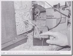
Always use an isolation transformer when servicing present-day TVs and CD and VCR players (Fig. 1-29). Most of these units are operated directly from the power line, and the chassis or some point in the chassis may be hot. Test instruments can be dam aged as well as the product that you are working on. Besides, you might receive a shock that can cause damage to your body, or you might accidentally pull an expensive test in strun1ent off the service bench.
when a TV set explodes and sets the house on fire, this can be very dangerous and fatal to the homeowner . If the fire spreads to the window curtains and to other rooms, someone can be trapped in the raging fire. Houses can be rebuilt . but a loved one is lost forever.
The electronics technician always should be careful when servicing an electronic chassis. Replace all safety- marked components with exact replacements. Never replace a flameproof resistor with a carbon resistor. Replace all line power supply and horizontal circuits with correct c0mponents. Make sure that cables and wires will not lie on hot components in the chassis. Inspect and replace a defective power cord. Always replace a fuse with one of the exact amperage.
Do not drop metal screws and small metal parts down into the maze of wiring and components and then forget to remove them before buttoning up the chassis. Make good, clean soldered connections. Botched wiring runs and poorly soldered connections may give the fire department and state commission an excuse to blame the electronics technician. In case of a death, you may lose everything you have worked for. Be careful out there.


