The Analogue Audio Waveform
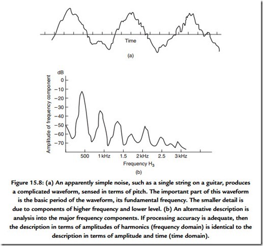
It seems appropriate to ensure that there is agreement concerning the meaning attached to words that are freely used. Part of the reason for this is in order that a clear understanding can be obtained into the meaning of phase. The analogue audio signal that we will encounter when it is viewed on an oscilloscope is a causal signal. It is considered as having zero value for negative time and it is also continuous with time. If we observe a few milliseconds of a musical signal we are very likely to observe a waveform that can be seen to have an underlying structure (Figure 15.8). Striking a single string can produce a waveform that appears to have a relatively simple structure. The waveform resulting from striking a chord is visually more complex, although, at any one time, a snapshot of it will show the evidence of structure. From a mathematical or analytical viewpoint the complicated waveform of real sounds is impossibly complex to handle and, instead, the analytical, and indeed the descriptive, process depends on us understanding the principles
through the analysis of much simpler waveforms. We rely on the straightforward principle of superposition of waveforms such as the simple cosine wave.
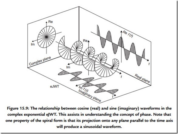
On its own an isolated cosine wave, or real signal, has no phase. However, from a mathematical point of view the apparently simple cosine wave signal, which we consider as a stimulus to an electronic system, can be considered more properly as a complex wave or function that is accompanied by a similarly shaped sine wave (Figure 15.9). It is worthwhile throwing out an equation at this point to illustrate this:
where f(t) is a function of time, t, which is composed of Re f(t), the real part of the function and j Im f(t), the imaginary part of the function and j is V-1.
Emergence of the V-1 is the useful part here because you may recall that analysis of the simple analogue circuit (Figure 15.10) involving resistors and capacitors produces an expression for the attenuation and the phase relationship between input and output of that circuit, which is achieved with the help of V-1.
The process that we refer to glibly as the Fourier transform considers that all waveforms can be considered as constructed from a series of sinusoidal waves of the appropriate amplitude and phase added linearly. A continuous sine wave will need to exist for all time in order that its representation in the frequency domain will consist of only a single frequency. The reverse side, or dual, of this observation is that a singular event, for example, an isolated transient, must be composed of all frequencies. This trade-off between the resolution of an event in time and the resolution of its frequency components is fundamental. You could think of it as if it were an uncertainty principle.
The reason for discussing phase at this point is that the topic of digital audio uses terms such as linear phase, minimum phase, group delay, and group delay error. A rigorous treatment of these topics is outside the scope for this chapter but it is necessary to describe them. A system has linear phase if the relationship between phase and frequency is a linear one. Over the range of frequencies for which this relationship may hold the systems, output is effectively subjected to a constant time delay with respect to its input. As a simple example, consider that a linear phase system that exhibits –180° of phase shift at 1 kHz will show –360° of shift at 2 kHz. From an auditive point of view, a linear phase performance should preserve the waveform of the input and thus be benign to an audio signal.
Most of the common analogue audio processing systems, such as equalizers, exhibit minimum phase behavior. Individual frequency components spend the minimum necessary time being processed within the system. Thus some frequency components of a complex signal may appear at the output at a slightly different time with respect to others.
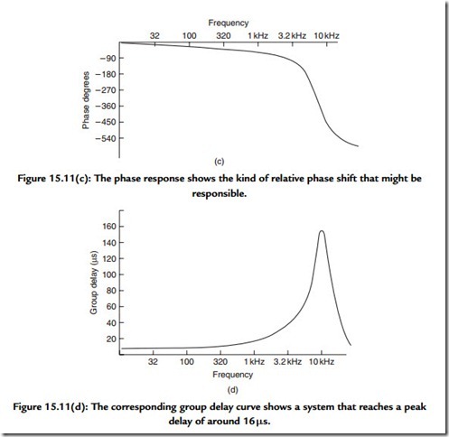
Such behavior can produce gross waveform distortion as might be imagined if a 2-kHz component were to emerge 2 ms later than a 1-kHz signal. In most simple circuits, such as mixing desk equalizers, the output phase of a signal with respect to the input signal is usually the ineluctable consequence of the equalizer action. However, for reasons which we will come to, the process of digitizing audio can require special filters whose phase response may be responsible for audible defects.
One conceptual problem remains. Up to this point we have given examples in which the output phase has been given a negative value. This is comfortable territory because such phase lag is converted readily to time delay. No causal signal can emerge from a system until it has been input, as otherwise our concept of the inviolable physical direction of time is broken. Thus all practical systems must exhibit delay. Systems that produce phase lead cannot actually produce an output that, in terms of time, is in advance of its input. Part of the problem is caused by the way we may measure the phase difference between input and output. This is commonly achieved using a dual-channel oscilloscope and observing the input and output waveforms. The phase difference is readily observed and can be readily shown to match calculations such as that given in Figure 15.10. The point is that the test signal has essentially taken on the characteristics of a signal that has existed for an infinitely long time exactly as it is required to do in order that our use of the relevant arithmetic is valid. This arithmetic tacitly invokes the concept of a complex signal, which is one which, for mathematical purposes, is considered to have real and imaginary parts (see Figure 15.9). This invocation of phase is intimately involved in the process of composing, or decomposing, a signal using the Fourier series. A more physical appreciation of the response can be obtained by observing the system response to an impulse.
Since the use of the idea of phase is much abused in audio at the present time, introducing a more useful concept may be worthwhile. We have referred to linear phase systems as exhibiting simple delay. An alternative term to use would be to describe the system as exhibiting a uniform (or constant) group delay over the relevant band of audio frequencies. Potentially audible problems start to exist when the group delay is not constant but changes with frequency. The deviation from a fixed delay value is called group delay error and can be quoted in milliseconds.
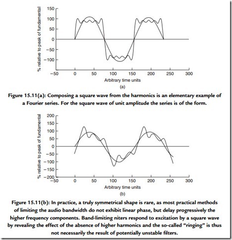
The process of building up a signal using the Fourier series produces a few useful insights [Figure 15.11(a)]. The classic example is that of the square wave and it is shown in Figure 15.11(a) as the sum of the fundamental, third and fifth harmonics. It is worth noting that
the “ringing” on the waveform is simply the consequence of band-limiting a square wave, that simple, minimum phase systems will produce an output rather like Figure 15.11(b), and there is not much evidence to show that the effect is audible. The concept of building up complex wave shapes from simple components is used in calculating the shape of
tidal heights. The accuracy of the shape is dependent on the number of components that we incorporate and the process can yield a complex wave shape with only a relatively small number of components. We see here the germ of the idea that will lead to one of the methods available for achieving data reduction for digitized analogue signals.
The composite square wave has ripples in its shape, due to band limiting, since this example uses only the first four terms, up to the seventh harmonic. For a signal that has been limited to an audio bandwidth of approximately 21 kHz, this square wave must be considered as giving an ideal response even though the fundamental is only 3 kHz. The 9% overshoot followed by a 5% undershoot, the Gibbs phenomenon, will occur whenever a Fourier series is truncated or a bandwidth is limited.
Instead of sending a stream of numbers that describe the wave shape at each regularly spaced point in time, we first analyze the wave shape into its constituent frequency components and then send (or store) a description of the frequency components. At the receiving end these numbers are unraveled and, after some calculation, the wave shape is reconstituted. Of course this requires that both the sender and the receiver of the information know how to process it. Thus the receiver will attempt to apply the inverse, or opposite, process to that applied during coding at the sending end. In the extreme it is possible to encode a complete Beethoven symphony in a single 8-bit byte. First, we must equip both ends of our communication link with the same set of raw data, in this case a collection of CDs containing recordings of Beethoven’s work. We then send the number of the disc that contains the recording which we wish to “send.” At the receiving end, the decoding process uses the received byte of information, selects the disc, and plays it. A perfect reproduction using only one byte to encode 64 minutes of stereo recorded music is created … and to CD quality!
A very useful signal is the impulse. Figure 15.12 shows an isolated pulse and its attendant spectrum. Of equal value is the waveform of the signal that provides a uniform spectrum. Note how similar these wave shapes are. Indeed, if we had chosen to show in Figure 15.12(a) an isolated square-edged pulse then the pictures would be identical, save that references to the time and frequency domains would need to be swapped. You will encounter these wave shapes in diverse fields such as video and in the spectral shaping of digital data waveforms. One important advantage of shaping signals in this way is that since the spectral bandwidth is better controlled, the effect of the phase response of a band-limited transmission path on the waveform is also limited. This will result in a waveform that is much easier to restore to clean “square” waves at the receiving end.


