INTERRUPTS
Interrupt overview
An interrupt is a hardware signal from a device to the associated CPU, telling it that the device needs attention. When a device asserts its interrupt request signal, it must be processed in an orderly fashion.
All CPUs, and other intelligent electronic devices, have some mechanism for enabling and disabling interrupt recognition and processing. At the device level, there is usually an interrupt control register with bits to enable or disable the interrupts that the device can generate. At the CPU level, a global mechanism functions to inhibit and enable (often called the global interrupt enable) recognition of interrupts. If the CPU is available, (it is not doing something else, such as servicing a higher-priority interrupt) it suspends the currently running task or thread, and then invokes the interrupt handler specified for that device within a required time gap. The job of the interrupt handler is to serve for the device, and stop it from interrupting. Once the handler returns, the CPU resumes whatever it was doing before the interrupt occurred.
Systems with multiple interrupt inputs provide the ability to mask (inhibit) interrupt requests individually and/or on a priority basis. This capability may be built into the CPU or provided by an external interrupt controller. Typically, there are one or more interrupt mask registers, with individual bits allowing or inhibiting individual interrupt sources. There is often also one non-maskable interrupt input to the CPU that is used to signal important conditions such as pending power fail, reset button pressed, or watchdog timer expiration.
(1) Interrupt specifications
An interrupt specification, also termed interrupt routing, is the information the system needs in order to link an interrupt handler with a given interrupt, and describes the information provided by the hard- ware to the system when making an interrupt request. Interrupt specifications typically includes a bus- interrupt level. For vectored interrupts it includes an interrupt vector.
When registering interrupts, the driver must provide the system with an interrupt number. This identifies which interrupt specification the driver is registering a handler for. Most devices have one interrupt; interrupt number zero, but there are devices that have different interrupts for different events. A communications controller may have one interrupt for receive ready and one for transmit ready. The device driver normally knows how many interrupts the device has, but if the driver has to support several variations of a controller it can call to find out the number of device interrupts. For a device with n interrupts, the interrupt numbers range from 0 to n-1.
Buses prioritize device interrupts at one of several bus-interrupt levels. These are then asso- ciated with different processor-interrupt levels. A bus-interrupt level that maps to a CPU interrupt priority level above the scheduler priority level is called a high-level interrupt. They must be handled without using system services that manipulate tasks or threads. A bus-interrupt level by itself does not determine whether a device interrupts at high level: a given bus-interrupt level may map to a high-level interrupt on one platform, but map to an ordinary interrupt on another. The driver can choose whether or not to support high-level interrupts, but it always has to check because it cannot assume that its interrupts are not high-level.
(2) Types of interrupts
There are two common ways to request an interrupt: vectored and polled. Both methods commonly specify a bus-interrupt priority level. Their only difference is that vectored devices also specify an interrupt vector, but polled devices do not.
(a) Vectored interrupts
Devices that use vectored interrupts are assigned an interrupt vector. This is a number that identifies that particular interrupt handler. This vector may be fixed, configurable (using jumpers or switches), or programmable. In the case of programmable devices, an interrupt device cookie is used to program the device interrupt vector. When the interrupt handler is registered, the kernel saves the vector in a table.
When the device interrupts, the system enters the interrupt acknowledge cycle, asking the interrupting device to identify itself. The device responds with its interrupt vector, and the kernel then uses this vector to find the responsible interrupt handler.
(b) Polled interrupts
In polled (or auto-vectored) devices, the only information the system has about a device interrupt is its bus-interrupt priority level. When a handler is registered, the system adds it to the list of potential interrupt handlers for the bus-interrupt level. When an interrupt occurs, the system must determine which device, of all the devices at that level, actually interrupted. It does this by calling all the interrupt handlers for that bus-interrupt level until one of them claims the interrupt.
(c) Software interrupts
Also known as soft interrupts, they are initiated by software rather than a device. Handlers for these interrupts must also be added to and removed from the system. Soft interrupt handlers run in interrupt context and therefore can be used to do many of the tasks that belong to an interrupt handler.
(3) Interrupt handlers
Modern CPUs use a general mechanism for processing exceptions, traps, and interrupts: an interrupt vector table. Some contain only the address of the code to be executed. In most cases, a specific ISR (interrupt service routine) is responsible for servicing each interrupting device and acknowledging, clearing, and rearming its interrupt; sometimes servicing the device (for example, reading data from a serial port) automatically clears and rearms the interrupt.
Hardware interrupt handlers are very quick, since they may suspend other system activity while running (particularly in high-level interrupt handlers). For example, they may prevent lower-priority interrupts from occurring while they run. For this reason they should do the minimum amount of work needed to service the device.
Software interrupt handlers run at a lower priority than hardware versions, so they can do more work without seriously impacting the performance of the system. If the hardware interrupt handler is high level, it is severely restricted in what it can do. In this case, it is a good idea to simply trigger a software interrupt in the high-level handler and put all possible processing into this handler. Software interrupt handlers must not assume that they have work to do when they run, since (like hardware interrupt handlers) they can run because some other driver triggered a soft interrupt. For this reason, the driver must indicate to the soft interrupt handler that it should do work before triggering the soft interrupt.
(4) Interrupt latency
Interrupts may occur at any time, but the CPU does not instantly recognize and process them. First, the CPU will not recognize a new interrupt while interrupts are disabled. Second, the CPU must, upon recognition, stop fetching new instructions and complete those still in progress.
Because the interrupt is totally unrelated to the program it interrupts, the CPU and ISR work together to save and restore the full state of the interrupted program (stack, flags, registers, and so on). The running program is not affected by the interruption, although it takes longer to execute.
Many interrupt controllers provide a means of prioritizing interrupt sources, so that, in the event of multiple interrupts occurring at (approximately) the same time, the more time-critical ones are pro- cessed first. These same systems usually also provide for prioritized interrupt handling, a means by which a higher-priority interrupt can interrupt the processing of a lower-priority interrupt. This is called interrupt nesting. In general, the ISR should only take care of the time-critical portion of the processing, then, depending on the complexity of the system, it may set a flag for the main loop, or use an operating system call to awaken a task to perform the non-time-critical portion.
The longest-period global interrupt recognition is inhibited. The longest-period global interrupt recognition may be due to these time factors: for example,the time it would take to execute all higher- priority interrupts if they occurred simultaneously; the time it takes the specific ISR to service all of its interrupt requests (if multiple ones are possible); the time it takes to finish the program instructions in progress and save the current program state and begin the ISR.
Interrupt handling
Handling interrupts is at the heart of a real-time and embedded control system. The actual process of determining a good handling method can be complicated, since numerous actions are occurring simultaneously at a single point, and have to be handled rapidly and efficiently. This subsection will provide a practical guide to designing an interrupt handler, and will discuss the various trade-offs between the different methods. The methods covered are (1) non-nested interrupt handler, (2) nested interrupt handler, (3) re-entrant nested interrupt handler, and (4) prioritized interrupt handlers.
(1) Non-nested interrupt handler
The simplest interrupt handler is a handler that is non-nested. This means that while handling an interrupt, all others are disabled until control is returned to the interrupted task or process. This type can only service a single interrupt at a time, and so are not suitable for complex embedded systems that service multiple interrupts with differing priority levels.
When the “Interrupt request” pin is raised, the microprocessor will disable further interrupts. It will then set the controller to point to the correct entry in the vector table and execute that instruction, which will alter the controller to point to the interrupt handler.
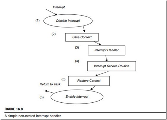
Once in the interrupt code, the interrupt handler has to first save the context, so that it can be restored on return. The handler can then identify the interrupt source and call the appropriate ISR. After servicing the interrupt the context can be restored, and the controller manipulated to point back to the next instruction before the interruption. Figure 16.8 shows the various stages that occur when an interrupt is raised in a system that has implemented a simple non-nested interrupt handler. Each stage is explained in more detail below:
(a) External source (e.g., from an interrupt controller) sets the interrupt flag. Processor masks further external interrupts and vectors to the interrupt handler through an entry in the vector table.
(b) On entry to the handler, the handler code saves the current context of the non-banked registers.
(c) The handler then identifies the interrupt source and executes the appropriate ISR.
(d) ISR services the interrupt.
(e) On return from the ISR the handler restores the context.
(f) Enables interrupts and return.
(2) Nested interrupt handler
A nested interrupt handler allows another interrupt to occur within the currently called handler. This is achieved by re-enabling interrupts before the handler has fully serviced the current one. This feature increases the complexity of the system, and so introduces the possibility of subtle timing issues that can cause system failure. These subtle problems can be extremely difficult to resolve, so the nested interrupt method has to be designed carefully. This is achieved by protecting the context restoration from interruption, so that the next interrupt will not fill (overflow) the stack, or corrupt any of the registers.
Standard problems can occur if nested interrupts are supported. One of these is a race condition, where a cascade of interrupts occurs, which will cause a continuous interruption of the handler until either the interrupt stack is full (overflowing) or the registers are corrupted. A designer has to balance efficiency with safety. This involves using a defensive coding style that assumes problems will occur, and check the stacking and protecting against register corruption where possible.
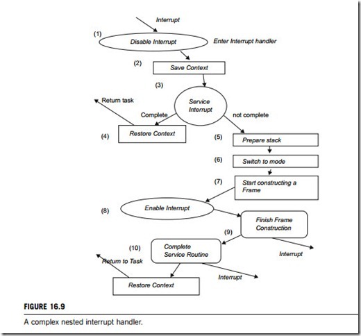
Figure 16.9 shows a nested interrupt handler. As can been seen from the diagram, the handler is quite a bit more complicated than the simple non-nested interrupt handler described above.
How stacks are organized is one of the first decisions a designer has to make when designing a nested interrupt handler. There are two fundamental methods that can be adopted either using
a single stack or multiple stacks. The multiple-stack method uses one stack for each interrupt or service routine. This increases the execution time and complexity of the handler. For a time-critical system, these tend to be undesirable characteristics.
The nested interrupt handler entry code is identical to the simple non-nested interrupt handler, except that on exit the handler tests a flag that is updated by the ISR that indicates whether further processing is required. If not, then the service routine is complete and the handler can exit. Otherwise the handler can take several actions; re-enabling interrupts and/or performing a context switch. Re-enabling interrupts involves switching out of interrupt request (IRQ) mode. We cannot simply re-enable interrupts in IRQ mode as this would lead to the link register being corrupted if an interrupt occurred after a branch with link instruction. This problem will be discussed in more detail below.
As a side note, performing a context switch involves flattening (emptying) the IRQ stack, as the handler should not perform a context switch while there are data on it unless the handler can maintain a separate IRQ stack for each task, which is, as mentioned previously, undesirable. All registers saved on the IRQ stack must be transferred to the task’s stack. The remaining registers must then be saved on the task stack. This is transferred to a reserved block on the stack called a stack frame.
(3) Re-entrant nested interrupt handler
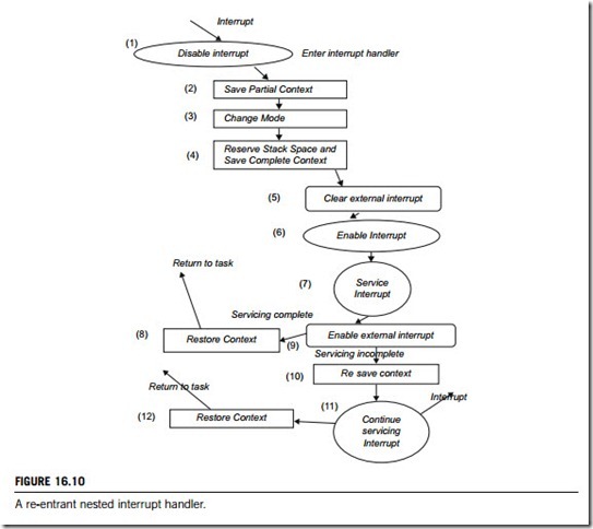
A re-entrant nested interrupt handler is a method of handling multiple interrupts that are filtered by priority (Figure 16.10). This is important since there is a requirement that interrupts with higher priority have a lower latency. This type of filtering cannot be achieved using the conventional nested interrupt handler. The basic difference between this type and a nested interrupt handler is that the interrupts are re-enabled early on in the interrupt handler to achieve low interrupt latency. There are a number of issues relating to re-enabling the interrupts early, which are described in more detail in the following paragraphs.
If interrupts are re-enabled in an interrupt mode, and the interrupt routine performs a subroutine call instruction (BL), the subroutine return address will be set in a special register. This address would be subsequently destroyed by an interrupt, which would overwrite the return address into this special register. To avoid this, the interrupt routine should swap into SYSTEM mode. The BL instruction can then use another register to store the subroutine address. The interrupts must be disabled at the source by setting a bit in the interrupt controller before re-enabling interrupts through the current processor status register (CPSR). If interrupts are re-enabled in the CPSR before pro- cessing is complete and the interrupt source is not disabled, an interrupt will be immediately regenerated, leading to an infinite interrupt sequence or race condition. Most interrupt controllers have an interrupt mask register that allows you to mask out one or more interrupts, leaving the remainder of the interrupts enabled.
The interrupt stack is unused since interrupts are serviced in SYSTEM mode (i.e., on the task’s stack). Instead the IRQ stack pointer is used to point to a 12-byte structure used to store some registers temporarily on interrupt entry. It is paramount for a re-entrant nested interrupt handler to operate effectively so the interrupts can be prioritized, otherwise the system latency degrades to that of a nested interrupt handler, because lower-priority interrupts will be able to preempt the servicing of a higher- priority interrupt. This can lead to the locking out of higher-priority interrupts for the duration of the servicing of a lower-priority interrupt.
(4) Prioritized interrupt handler
There are four types of prioritized interrupt handler which provide different handling strategies, as given below:
(a) Simple prioritized interrupt handler
Both the simple and nested interrupt handler service interrupts on a first-come first-served basis, whereas a prioritized interrupt handler will associate a priority level with a particular interrupt source. This is used to dictate the order that the interrupts will be serviced, and means that a higher-priority interrupt will take precedence over a lower-priority interrupt, which is desirable in an embedded system.
Prioritization can be achieved either in hardware or in software. Hardware prioritization means that the handler is easier to design, since the interrupt controller will provide the current highest-priority interrupt which requires servicing. These systems require more initialization code, since the interrupts and associated priority-level tables have to be constructed before the system can be switched on. Software prioritization requires an external interrupt controller, which has to provide a minimal set of functions, including being able to set and unset masks and read interrupt status and source. For software systems the rest of this subsection will describe a priority interrupt handler, and to help with this a fictional interrupt controller will be used. With the Intel Pentium series, the interrupt controller takes in multiple interrupt sources and will generate an IRQ and/or FIQ signal depending on whether a particular interrupt source is enabled or disabled.
The interrupt controller has a register that holds the raw interrupt status (IRQRawStatus). A raw interrupt is an interrupt that has not been masked by a controller. IRQEnable register determines which interrupts are masked from the microprocessor. This register can only be set or cleared using IRQEnableSet and IRQEnableClear. Table 16.2 shows a summary of the register set names and the types of operation (read/write) that can occur with it. Most interrupt controllers also have
a corresponding set of registers for FIQ; some can also be programmed to select the type of interrupt distinction, i.e., select the type of interrupt raised (IRQ/FIQ) from a particular interrupt source.
(b) Standard prioritized interrupt handler
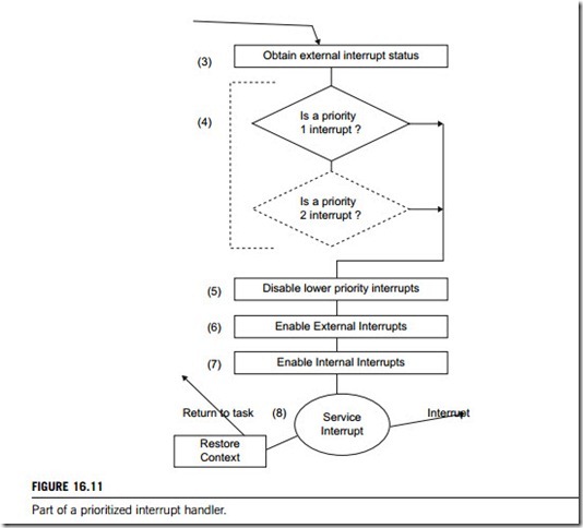
A simple priority interrupt handler tests all the interrupts to establish the highest priority. An alternative solution is to branch early when the highest-priority interrupt has been identified. The prioritized interrupt handler follows the same entry code as for the simple prioritized interrupt handler. The prioritized interrupt handler has the same start as a simple prioritized handler but intercepts the interrupts with a higher priority earlier. Figure 16.11 gives the part of the algorithm applied to the standard prioritized interrupt handler.
(c) Direct prioritized interrupt handler
A direct prioritized interrupt handler branches directly to the ISR. Each of these is responsible for disabling lower-priority interrupts before modifying the CPSR so that interrupts are re-enabled. This type of handler is relatively simple, since the masking is done by the service routine. This causes minimal duplication of code since each service routine is effectively carrying out the same task.
(d) Grouped prioritized interrupt handler
Lastly, the grouped priority interrupt handler is assigned a group priority level for a set of interrupt sources, sometimes important when there is a large number of them. It tends to reduce the complexity of the handler since it is not necessary to scan through every interrupt to determine the priority level. This may improve the response times.
Enable and disable interrupts
Interrupt masking allows us to disable the detection of an interrupt-line assertion, which causes the operating system or kernel to ignore an interrupt signal. The signal can be ignored at the micro- processor level (or CPU level) or at other levels in the hardware architecture. In some cases, each interrupt source in the system can be masked individually. In other cases, masking an interrupt in a microprocessor register can mask a group of interrupts. An example of this is multiple interrupts.
When an interrupt occurs, the microprocessor must globally disable interrupts at the micro- processor level to avoid being interrupted while gathering and saving interrupt state information. Because disabling interrupts globally blocks all other interrupts, masking should take place for as
short a time as possible. When you determine what has specifically interrupted, you can mask just that interrupt.
A maskable interrupt is essentially a hardware interrupt that may be ignored by setting a bit in an interrupt mask register’s (IMR) bit-mask. Similarly, a non-maskable interrupt is a hardware interrupt that typically does not have a bit-mask associated with it.
All the regular interrupts that we normally use and refer to by number are called maskable interrupts. The processor is able to mask, or temporarily ignore, any interrupt if it needs to, to finish something else that it is doing. In addition, however, there is a non-maskable interrupt (NMI) that can be used for serious conditions that demand the microprocessor’s immediate attention. The NMI cannot be ignored by the system unless it is shut off specifically.
When an NMI signal is received, the microprocessor immediately drops whatever it was doing and attends to it. As you can imagine, this could cause crashes if used improperly. In fact, the NMI signal is normally used only for critical problem situations, such as serious hardware errors. Its most common
use is to signal a parity error from the memory subsystem, which must be dealt with immediately to prevent possible data corruption.
Interrupt vector
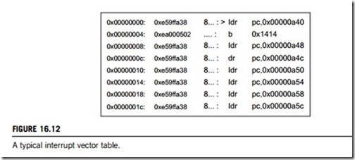
As mentioned in Chapter 5, the interrupt vector table can start at memory address 0x00000000. A vector table consists of a set of assembler (or machine) instructions, which cause the controller or computer to jump to a specific location that can handle a specific exception or interrupt. A vector uses a special assembler instruction to load the address of the handler. The address of the handler will be called indirectly, whereas a branch instruction will go directly to the handler. When booting a system, quite often the read-only memory (ROM) is located at 0x00000000. This means that when SRAM is remapped to location 0x00000000 the vector table has to be copied to SRAM at its default address prior to the remap, normally achieved by the system initialization code. SRAM is normally remapped because it is wider and faster than ROM; it also allows vectors to be dynamically updated as requirements change during program execution.
Figure 16.12 shows a typical vector table of a real system. The undefined instruction handler is located so that a simple branch is adequate, whereas the other vectors require an indirect address using assembler instructions specific for loading.
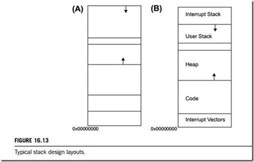
Where the interrupt stack is placed depends on the real-time operating system (RTOS) require- ments and the specific hardware being used. The example in Figure 16.13 shows two possible stack layouts, firstly (A) shows the traditional stack layout with the interrupt stack being stored underneath the code segment. The second, layout (B), shows the interrupt stack at the top of the memory above the user stack. This has the advantage that the stack grows into the user stack and thus does not corrupt the vector table. For each mode, a stack has to be set up, carried out every time the processor is reset.
If the interrupt stack expands into the interrupt vector, the target system will crash, unless some means exists to handle this error when it occurs.
Before an interrupt can be enabled, the IRQ mode stack has to be set up, normally, in the initialization code for the system. It is important that the maximum size of the stack is known, since that size can be reserved for the interrupt stack.
Interrupt service routines
An interrupt service routine (ISR) is a software routine that hardware invokes in response to an interrupt. ISR examines an interrupt and determines how to handle it executes the handling, and then returns a logical interrupt value. If no further handling is required the ISR notifies the kernel with a return value. An ISR must perform very quickly to avoid slowing down the operation of the device and the operation of all lower-priority ISRs.
Although an ISR might move data from a CPU register or a hardware port into a memory buffer, in general it relies on a dedicated interrupt thread (or task), called the interrupt service thread (IST), to do most of the required processing. If additional processing is required, the ISR returns a logical interrupt value to the kernel. It then maps a physical interrupt number to a logical interrupt value. For example, the keyboard might be associated with hardware interrupt 4 on one device and hardware interrupt 15 on another device. The ISR translates the hardware-specific value to the standard value corresponding to the specific device.
When an ISR notifies the kernel of a specific logical interrupt value, the kernel examines an internal table to map the logical interrupt value to an event handle. The kernel then wakes the IST by signaling the event. An event is a standard synchronization object that serves as an alarm clock to wake up a thread when something interesting happens.
The interrupt service thread is a thread that does most of the interrupt processing. The operating system wakes the IST when it has an interrupt to process, otherwise, it remains idle. For the operating system to wake the IST, the IST must associate an event object with an interrupt identifier. After an interrupt is processed, the IST should wait for the next interrupt signal. This call is usually inside a loop.
When a hardware interrupt occurs, the kernel signals the event on behalf of the ISR, and then the IST performs necessary I/O operations in the device to collect the data and process them. When the interrupt processing is completed, the IST informs the kernel to re-enable the hardware interrupt.
An interrupt notification is a signal from an IST that notifies the operating system that an event must be processed. For devices that connect to a platform through intermediate hardware, the device driver for that hardware should pass the interrupt notification to the top-level device driver. Generally, the intermediate hardware’s device driver has some facility that allows another device driver to register a call-back function, which the intermediate device driver calls when an interrupt occurs.
As an example, PC cards connect to hardware platforms through a PC card slot, which is an intermediate piece of hardware with its own device driver. When a PC card device sends an interrupt, it is actually the PC card slot hardware that signals the physical interrupt on the system bus. The device driver for the PC card slot has an ISR and IST that handle the physical interrupt. They use a function to pass the interrupt to the device driver for the PC card device. Devices with similar connection methods behave similarly.
