MODULATION
A radio wave is a sine wave of voltage that has been converted into electric and magnetic fields by the antenna. The transmitter generates the sine wave and amplifies it to a high power level. The question is, how does the informaion to be transmitted fit into this?
The information or intelligence to be conveyed is usually a voice signal produced by a microphone. Other forms of intelligence signals include pictures or video and digital (binary) data from a computer. The purpose of the high-frequency sine wave radio signal is to give the intelligence signal a ride. That’s why the radio signal generated by the transmitter is called the carrier. Modulation is the process by which the information is impressed on or embedded in the carrier. Modulation causes the carrier to be modified by the information signal.
There are three basic forms of modulation used to put information on a carrier: amplitude modulation (AM), frequency modulation (FM), and phase modulation (PM).
Amplitude Modulation
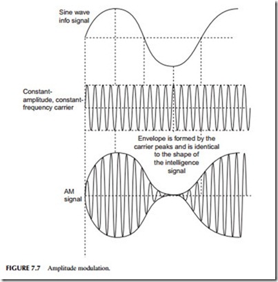
In amplitude modulation, the voltage or power level of the information signal changes the amplitude of the carrier in proportion (see Figure 7.7 ). With no modulation, the AM carrier is transmitted by itself. When the modulating information signal (a sine wave) is applied, the carrier amplitude rises and falls in accordance. The carrier frequency remains constant during amplitude modulation.
Amplitude modulation is widely used in radio. AM broadcast stations are, of course, amplitude modulated. So are citizens band radios, aircraft radios, and the video modulation of a TV broadcast transmitter. A special form of amplitude modulation, known as quadrature modulation (QAM), is also widely used in modems to transmit digital data over cable or wireless.
Sidebands
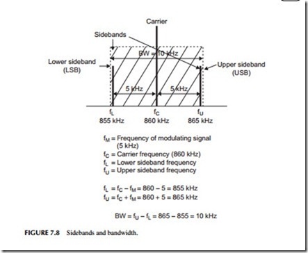
The modulation process causes new signals to be generated. These new sine wave signals are called sidebands. Their frequencies are the sum and differ- ence of the carrier and modulating signal frequencies. For example, in an AM radio station, audio frequencies as high as 5 kHz can be transmitted. If a 5-kHz sine wave tone is to be transmitted, the modulation process causes sidebands 5 kHz below and 5 kHz above the carrier to be produced. This is illustrated in Figure 7.8. For an AM radio station with a carrier frequency of 860 kHz, the
lower sideband (LSB) would occur at 860 – 5 = 855 kHz, while the upper sideband (USB) occurs at 860 + 5 = 865 kHz. The carrier and the sidebands combined produce the composite waveform shown at the bottom of Figure 7.7.
Bandwidth
This brings up the very important concept of bandwidth. Bandwidth refers to a range of frequencies over which a radio signal operates. This is also referred to as a radio channel. As you can see from Figure 7.8, the AM signal consists of the carrier and the sidebands. Together these signals occupy a bandwidth of 10 kHz. You can figure out the bandwidth of any signal by simply subtracting the lower sideband frequency from the upper sideband frequency.
All of the receiver circuits must be set to pass signals in this 10-kHz range in order to avoid distortion of the signal or lost information.
Frequency Modulation
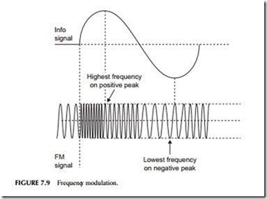
In frequency modulation, the carrier amplitude remains constant but its frequency is changed in accordance with the modulating signal. Specifically, the higher the amplitude of the information signal, the greater the frequency change. The actual carrier frequency deviates above and below the center carrier frequency as the information signal amplitude varies. Figure 7.9 shows frequency modulation with a sine wave information signal. Note that the carrier frequency gets higher on the positive peaks and lower on the negative peaks of the information signal.
Like AM, FM also produces sidebands. But unlike AM, which produces a single pair of sidebands for each frequency in the modulating signal, the frequency-modulation process produces an infinite number of pairs of side- bands for each frequency in the information signal. As a result, the bandwidth occupied by an FM signal is enormous. Luckily, the number of sidebands produced can be controlled by properly selecting the amount of deviation per- mitted in the carrier. Small deviations result in fewer sidebands. Further, some of the higher-order sidebands are extremely low in amplitude and, therefore, contribute little to the FM signal. But while the bandwidth of an FM signal can be controlled and established to fit a desired frequency range, it does nevertheless usually take more room in the spectrum than an AM signal.
The primary benefit of FM is that it is less sensitive to noise, which consists of undesirable amplitude variations that get involuntarily added to a signal. Noise is easily eliminated in an FM system where a constant carrier amplitude is used. Some of the most common applications of FM include FM radio broadcasting, and two-way mobile and marine radios.
Phase Modulation
The third type of modulation is phase modulation. Remember that phase shift is a time shift between two sine waves of the same frequency. We can use the information signal to shift the phase of the carrier with respect to the carrier reference. The result of this, however, is a signal that looks virtually the same as an FM signal (Figure 7.9). Phase modulation is usually a little easier to implement electronically than FM, so most so-called FM systems typically use phase modulation instead. Both FM and PM are often referred as types of angle modulation.
Digital Modulation
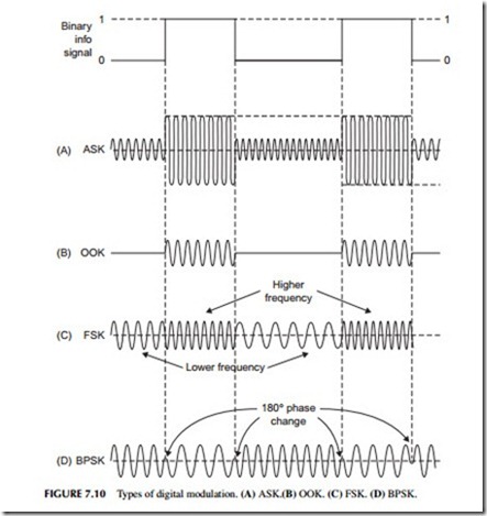
All of the three basic types of modulation, AM, FM, and PM, can also be used to transmit digital or binary data. However, they are usually given different names. Amplitude modulation of a carrier by a binary signal is usually referred to as amplitude shift keying (ASK). This is illustrated in Figure 7.10A . The binary signal simply shifts the carrier amplitude between two specific levels. A special form of ASK is called on–off keying (OOK). This is illustrated in Figure 7.10B. Here the binary signal simply turns the carrier on for a binary 1 and off for a binary 0.
Frequency modulation of a carrier by a binary signal is called frequency shift keying (FSK). Here the binary signal shifts the carrier between two dis- crete frequencies (see Figure 7.10C).
Phase modulation of a carrier by a binary signal is referred to as phase shift keying (PSK). The term binary PSK (BPSK) is also used. The phase of the carrier is changed as the binary signal switches from 0 to 1 or 1 to 0 (see Figure 7.10D). Phase shift is 180 degrees, which is easily detected at the receiver.
One of the most widely used forms of digital modulation is QAM, which is really a composite of both AM and PSK. The binary signal is converted into a multilevel digital signal that simultaneously modifies both the amplitude and the phase of the signal. QAM is used in digital data transmission in satellites and in modems sending digital data in audio form over telephone lines or cable TV systems. It is also widely used in the newer digital wireless networks. See Chapter 8 for more detail.
Because binary signals contain many higher-frequency harmonics, the resulting signals produced by modulation have an enormous bandwidth. Many schemes have been developed to limit the spectrum of the modulating signal and, as a result, to reduce the amount of bandwidth occupied by a binary modulated radio signal.
Spread Spectrum
Spread spectrum (SS) is unusual in that it is not only a form of modulation but also a system for encrypting the information signal for security purposes and for multiplexing multiple signals over a range of frequencies.
Spread spectrum was originally developed during World War II as a way to prevent the enemy from interpreting radio transmissions. For years the government and military protected the concepts of SS modulation. However, today it is widely used in radio and telephone communications. Most of the newer cellular telephones are based on this concept, specifically code division multiple access (CDMA) cell phones.
When using SS, the analog information signal is converted into a digital signal before transmission. The digital voice signal is then used to modify the carrier in a special way. The two most common ways of modifying the carrier are referred to as direct-sequence (DS) and frequency-hopping (FH) spread spectrum. In direct-sequence SS, the serial digital signal representing the voice is chopped up into random sequences and then used to PSK the carrier. In frequency-hopping SS, the carrier is rapidly switched from one frequency to another for a short dwell time. The result of SS modulation is that the signal itself is broken up at random, and spectral energy is spread over a very wide frequency range. Because of the random sequences of the coding and frequency hopping, such a radio signal is nearly impossible to put back together at a receiver without knowing the code. SS receivers designed to pick up the SS signal know the code, and can unscramble the signal and reassemble it into the original modulating information signal.


