ANTENNAS
The antenna takes the voltage and current produced by the transmitter and converts it into the electromagnetic wave we know as a radio wave. At the receiver, the antenna converts the electromagnetic field back into a voltage we know as the radio signal. The radio waves pass over the receiving antenna, inducing a voltage that causes current to flow in the receiver.
Antennas can have an amazing variety of shapes. Essentially an antenna or aerial is some arrangement of electrical conductors whose size and length are critical. For optimum operation, the antenna length must be related to the wavelength (λ) of the signal. Common antenna sizes are one-quarter (λ/4) and one-half (λ/2) wavelength at the operating frequency. The higher the frequency, the shorter the wavelength and thus the smaller the antenna. For example, one wavelength at 150 MHz, a popular two-way radio frequency range measures 2 meters. A half wavelength is 1 meter and a quarter wavelength is 0.5 meter. Since 1 meter is 39.37 inches, a half wavelength is 19.68 inches. At 900 MHz, the frequency range of cell phones, one wavelength is 0.3333 meter. A quarter wavelength antenna would be 0.3333/4 = 0.08333 meter or 3.28 inches.
Ground-Plane Antenna
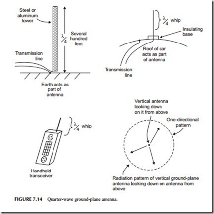
Antennas can be anywhere from a long horizontal copper wire to a vertical steel or aluminum tower several hundred feet tall. Or it may be an array of short conductors like those in a TV antenna. One of the most common antennas is a short quarter wavelength vertical that is widely used in mobile radios, cell phones, and other hand-held units (see Figure 7.14). The quarter-wave or ground-plane antenna as it is sometimes called, radiates equally well in all directions, making it omnidirectional. We say that its radiation or reception pattern is a circle.
Dipole
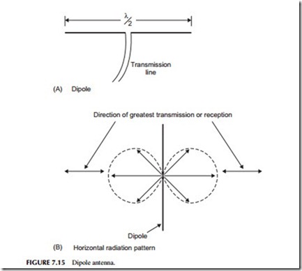
Another common antenna type is the dipole, which is one-half wavelength long and usually mounted horizontally. Figure 7.15 shows an example. Its radiation or reception pattern is a figure 8. The greatest radiation or strongest reception occurs at a right angle to the dipole element itself.
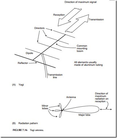
slightly longer than one-half wavelength, and one or more director elements that are progressively shorter than the dipole. The directors and reflector make the Yagi highly directional. The extra elements, called parasitic elements, concentrate and aim the beam of radiation over a narrow range. At the transmitter, this has the effect of increasing the transmitted power, making the signal stronger at the receiver as if the transmitter power had been increased. A similar gain effect occurs at the receiver.
Other Antennas
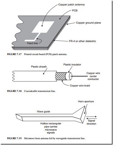
There are many other antenna variations. Antennas formed with copper pat- terns on a printed circuit board (PCB) are widely used. One example is the patch antenna (see Figure 7.17). It is simply a square area of copper about one-half wavelength on a side made on a PCB. Another is the loop antenna that is just a loop of copper on the PCB. A popular cell phone antenna is the
inverted F, which is an F-shaped pattern on the PCB. Antennas also come as components. For microwave frequencies, there are special antennas made on a ceramic base that are small and can be soldered to a PCB.
Transmission Lines
The antenna is usually connected to the transmitter or receiver by way of a coaxial cable (see Figure 7.18 ). It consists of a copper center conductor surrounded by an insulator, such as Teflon. Around that is a shielded copper braid or foil. The whole thing is covered with a plastic insulator. Coaxial cable is the most commonly used transmission line to connect the equipment to the antenna. It provides an efficient method of transferring the voltages and currents to and from the antenna while providing a certain amount of shielding from noise. For PCB antennas, the transmission line is just a short pair of cop- per lines from the transceiver IC to the antenna.
Microwave Antennas and Waveguides
Antennas used at microwave frequencies are quite different from those used at the lower frequencies. Perhaps the most common is the horn antenna. It looks
like the flared end of a musical horn, only most of them have an opening or aperture that is rectangular rather than round.
As seen in Figure 7.19, the horn is directional and has gain. The microwave energy is fed to the horn by a transmission line. Coax can be used for the lower microwave frequencies, but at the higher microwave frequencies, coaxial cable loss is too high for long runs. A high percentage of the signal power is lost in the coax cable itself. This problem is overcome by using a waveguide. A waveguide is nothing more than a hollow copper pipe, usually with a rectangular cross-section through which the microwave energy passes from transmitter to antenna or from antenna to receiver.
Signal direction
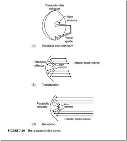
The most effective and widely used microwave antenna is the parabolic dish (see Figure 7.20). This is usually a horn antenna combined with a reflector shaped like a dish. Its shape is a mathematical parabola. Signals transmit- ted by the horn are reflected forward by the parabolic dish shaping the radio waves into a very narrow beam. Received energy is reflected by the dish into the horn antenna. The highly directional nature of the dish gives it a very
narrow beamwidth and enormous gain. These are widely used in satellite TV and radar.
