Parameters of the Programmable Controller
Before the program can be developed, the parameters of the programmable controller being used must be known. Because the SERIES ONE programmable controller is being used in this example, its parameters will be discussed. An operations and programming guide for the SERIES ONE is shown in Figure 54 – 12. All coil and I/O references must be entered in OCTAL. OCTAL is a number system that contains only eight digits, 0 through 7. The numbers 8 and 9 are not used because they do not exist as far as the computer is concerned. This does not mean that the numbers 8 and 9 cannot be used when entering times for a timer, it ap- plies only to the way inputs, outputs, and internal relays are identified. For example, any programmable controller that is octal base will not use the numbers 8 or 9. The I/O points for this unit are 000 through 157. Assume the first I/O module used with this controller contains eight units, and these eight units are inputs. The inputs will number from 0 to 7. Now, assume the next set of I/Os is an output module. Numbers 10 through 17 can be used as an output. Notice that numbers 8 and 9 are omitted. The programming guide indicates that a total of 144 internal coils exists. Coils 160 through 337 are nonretentive and coils 340 through 373 are retentive. There are a total of 64 timers and counters, which begin with 600 and go through 677. Remember that there are no 8s or 9s. After timer 607 is used, the next timer will be 610.
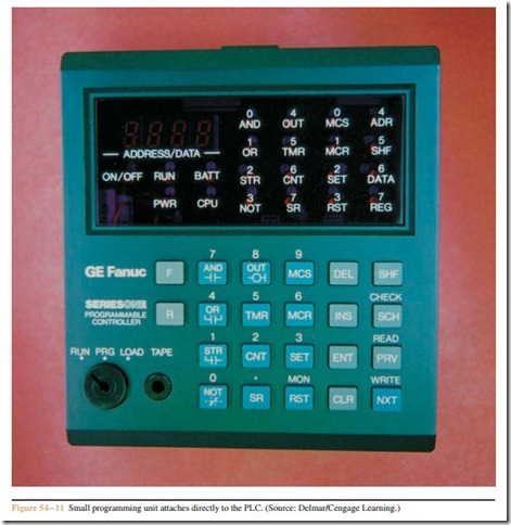
The circuit shown in Figure 54 – 13 will be programmed into the controller using the small programming unit. The contacts labeled 0 and 1 are inputs. Con- tact 0 is connected to the normally open pressure switch, which is used to sense the high pressure condition. Con- tact 1 is connected to the normally open push button used to acknowledge the fault and to turn off the audible alarm. Coils 10 and 11 are outputs. Coil 10 is connected to the warning light and coil 11 is connected to the audible alarm. Coils T600 and T601 are timers used to produce the flashing action of the warning light. In this circuit, the warning light will be on for 0.5 second and off for 0.5 second. Coil 160 is an internal relay.
