Objectives
After studying this unit, the student will be able to:
• Convert a relay schematic to a schematic used for programming a PC
• Enter a program into a programmable controller
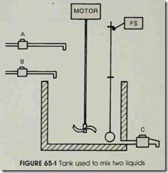
In this unit a relay schematic will be con verted into a diagram used to program a pro grammable controller. The process to be con trolled is shown in figure 65-1. A tank is used to mix two liquids. The control circuit operates as follows:
A. When the start button is pressed, solenoids A and B energize. This permits the two liq uids to begin filling the tank.
B. When the tank is filled, the float switch trips. This de-energizes solenoids A and B and starts the motor used to mix the liquids together.
C. The motor is permitted to run for one min ute. After one minute has elapsed, the motor turns off and solenoid C energizes to drain the tank.
D. When the tank is empty, the float switch de energizes solenoid C.
E. A stop button can be used to stop the pro cess at any point.
F. If the motor becomes overloaded, the action of the entire circuit will stop.
G. Once the circuit has been energized it will continue to operate until it is manually stopped.
CIRCUIT OPERATION
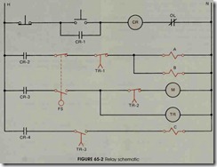
A relay schematic that will perform the logic of this circuit is shown in figure 65-2. The logic of this circuit is as follows:
A. When the start button is pushed, relay coil CR is energized. This causes all CR contacts to close. Contact CR-1 is a holding contact used to maintain the circuit to coil CR when the start button is released.
B. When contact CR-2 closes, a circuit is com pleted to solenoid coils A and B. This per mits the two liquids that are to be mixed to gether to begin filling the tank.
C. As the tank fills, the float rises until the float switch is tripped. This causes the normally closed float switch contact to open and the normally open contact to close.
D. When the normally closed float switch opens, solenoid coils A and B de-energize and stop the flow of the two liquids into the tank.
E. When the normally open contact closes, a circuit is completed to the coil of a motor starter and the coil of an on-delay timer. The motor is used to mix the two liquids together.
F. At the end of the one minute time period, all of the TR contacts change position. The normally closed TR-2 contact connected in series with the motor starter coil opens and stops the operation of the motor. The nor mally open TR-3 contact closes and ener gizes solenoid coil C which permits liquid to begin draining from the tank.. The normally closed TR-1 contact is used to assure that valves A and B cannot be re-energized until solenoid C de-energizes.
G. As liquid drains from the tank, the float drops. When the float drops far enough, the float switch trips and its contacts return to their normal positions. When the normally open float switch contact reopens and de-en ergizes coil TR, all TR contacts return to their normal positions.
A. When the normally open TR-3 contact re opens, solenoid C de-energizes and closes the drain valve. Contact TR-2 recloses, but the motor cannot restart because of the nor mally open float switch contact. When con tact TR-1 recloses, a circuit is completed to solenoids A and B. This permits the tank to begin refilling, and the process starts over again.
I. If the stop button or overload contact opens, coil CR de-energizes and all CR contacts open. This de-energizes the entire circuit.
DEVELOPING A PROGRAM
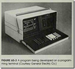
This circuit will now be developed into a pro gram which can be loaded into the programmable controller. Figure 65-3 shows a program being de veloped on a programming terminal. Assume that the controller has an 110 capacity of 32, that 110 terminals 1 through 16 are used as inputs, and that terminals 17 through 32 are used as outputs.
The first line of the relay schematic in figure 65-2 shows a normally closed stop button con nected in series with a normally open start button. A normally open CR contact is connected parallel to the start button, and coil CR and the normally closed overload contact are connected in series with the start button.
Figure 65-4 shows lines 1 and 2 of the program which will be used to program the PC. Contact #1 is controlled by the normally closed stop push but ton connected to terminal # 1 of the 110 track. Notice that contact # 1 is programmed normally open instead of normally closed. Since the stop button is a normally closed push button, power will be applied to terminal # 1 of the 110 track during the normal operation of the circuit. When power is applied to an input terminal of the 110 track, the central processing unit interprets it as an instruction to change the position of the contact that corresponds to that terminal number. There fore, the CPU will interpret contact # 1 to be closed during the normal operation of the circuit.
Contact #2 is connected to the normally open start button. Contact #3 is connected to a nor mally closed overload contact. Notice that this contact is programmed normally open for the same reason that contact # 1 is programmed nor mally open. Notice also that the position of the overload contact has been changed from the right side of the coil to the left side. This is done be cause a coil ends the line of a program. All con tacts used to control a coil must be placed ahead of it. The coil is assigned #33. Since this pro grammable controller has an 110 capacity of 32, coil 33 is an internal relay.
The normally open contact 33 is connected parallel to contact #2. Although this contact is the only component on the line, it counts as one full line of the program.
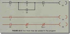
In figure 65-5 two more lines have been added to the program. Contact #4 is connected to the float switch. The float switch controls the op eration of internal relay 34. Internal relay 35 is controlled by contacts 33, 34, and T0-1.
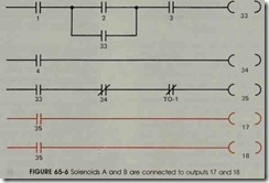
Figure 65-6 shows the addition of two more lines of the program. When internal relay 35 is energized, outputs 17 and 18 turn on. Solenoid coil A is connected to terminal 17 of the 1/0 track and solenoid coil B is connected to terminal 18.
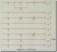
Figure 65-7 shows the complete program. Coil 19 controls output 19 which is connected to the coil of a motor starter. Coil T0-1 is an internal timer that has been programmed for 600 tenths of a second, or 60 seconds. Coil 20 controls output 20 which is connected to solenoid coil C.
OPERATION OF THE PC CIRCUIT
This circuit operates as follows:
A. Since the stop button and the overload con tact are normally closed, inputs #1 and #3 have continuous voltage applied to them. The central processing unit, therefore, inter prets contacts # 1 and #3 to be closed.
B. . When the start button is pushed, contact #2 closes, completing a circuit to coil 33.
C. When coil 33 energizes, all 33 contacts close.
The start button can now be released and the circuit will be maintained by the 33 con tact connected parallel to contact #2. Inter nal relay coil 35 energizes when a 33 contact closes.
A. When contacts 35 close, coils 17 and 18 en ergize. This permits solenoids A and B to energize and begin filling the tank with liquid.
B. When the float rises high enough, the float switch activates and supplies power to ter minal #4 of the 110 track. The CPU inter prets contact #4 to be closed, which causes internal relay coil 34 to energize.
C. The normally closed 34 contact opens and de-energizes coil 35. This causes both of the 35 contacts to open and de-energize coils 17 and 18. When output terminals 17 and 18 turn off, solenoids A and B de-energize.
When the normally open 34 contactcloses, coil 19 energizes, which connects power to the motor starter coil, and timer coil T0-1 energizes and starts the 60-second timer.
At the end of the 60-second time period, all T0-1 contacts change position. One of the normally closed contacts opens and prevents coil 35 from energizing until the timer has been reset. The other normally closed con tact opens and de-energizes output 19 which de-energizes the motor starter coil to stop the mixing motor. The normally open T0-1 contact closes and energizes output 20. This output energizes solenoid C which begins draining the tank. As liquid drains from the tank, the float drops. When the float drops far enough, the float switch opens and breaks the circuit to input terminal #4. This causes contact #4 to open and de energize coil 34.
I. When coil 34 de-energizes, all 34 contacts re turn to their normal positions. This causes coil T0-1 to de-energize and all T0-1 con tacts to return to their normal positions.
J. This de-energizes coil 20 which turns off so lenoid C, and completes the circuit to coil 35. When coil 35 energizes, outputs 17 and 18 turn on and energize solenoids A and B to start the process over again.
K. If the stop push button is pushed or if the overload contact opens, coil 33 will de-en ergize and stop the operation of the circuit.
Notice that this circuit operates with the same logic as the relay circuit. The circuit in figure 65-7 is now ready to be programmed into the con troller. Push buttons located on the programming terminal which represent open and closed contacts, coils and timers are used to insert the program into the central processing unit.
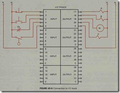
Figure 65-8 shows the connection of external components to the 110 track. The push buttons, the overload contact, and the float switch are con nected to the input terminals. The solenoid coils and the motor starter coil are connected to the output terminals.
PROGRAMMING IN BOOLEAN
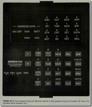
The preceding example circuit was developed for one specific type of programmable controller. It was intended as an example of how to develop and enter a program into the logic of the CPU us ing a programming terminal similar to the one shown in figure 64-4A. There may be times when it is necessary to use a small programming device which is hand held or which attaches directly to the CPU when entering a program. A unit of this type is shown in figure 65-9. This programming unit can be used with the SERIES ONE group of programmable controllers manufacture by GE Fanuc Automation. The following program will be developed for entry into the SERIES ONE using the hand-held programmer.
DEVELOPING THE PROGRAM
The following program will be used as a trou ble annunciator: A pressure switch is to be con nected to the input of a programmable controller. When the pressure rises to a preset point, an au dible alarm will be sounded and a warning light will flash on and off. When the operator acknowl edges the trouble, the audible alarm will be si lenced, but the warning light will continue to flash on and off until the pressure returns to a safe level.
PARAMETERS OF THE PROGRAMMABLE CONTROLLER
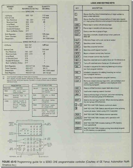
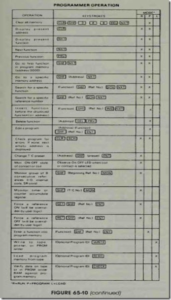
Before the program can be developed, the pa rameters of the programmable controller being used must be known. Because the SERIES ONE programmable controller is being used in this ex ample, its parameters will be discussed. An oper ations and programming guide for the SERIES ONE is shown in figure 65-10. All coil and 110 references must be entered in OCTAL. OCTAL is a number system which contains only eight digits, 0 through 7. The numbers 8 and 9 are not used be cause they do not exist as far as the computer is concerned. – This does not mean that the numbers 8 and 9 cannot be used when entering times for a timer. This applies only to the way inputs, out puts, and internal relays are identified. For exam ple, any programmable controller that is octal base will not use the numbers 8 or 9. The 110 points for this unit are 000 through 157. Assume the first 110 module used with this controller contains eight units, and these eight units are inputs. The inputs will number from 0 to 7. Now, assume the next set of I/O’s is an output module. Numbers 10 through 17 can be used as an output. Notice that numbers 8 and 9 are omitted. The programming guide indicates that a total of 144 internal coils ex ists. Coils 160 through 337 are nonretentive and coils 340 through 373 are retentive. There are a total of 64 timers and counters which begin with 600 and go through 677. Remember that there are no 8s or 9s. After timer number 607 is used, the next timer will be 610.
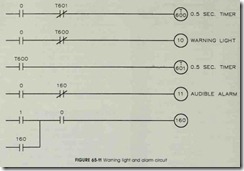
The circuit shown in figure 65-11 will be programmed into the controller using the small pro gramming unit. The contacts labeled 0 and 1 are inputs. Contact 0 is connected to the normally open pressure switch which is used to sense the high pressure condition. Contact 1 is connected to the normally open push button used to acknowl edge the fault and to turn off the audible alarm. Coils 10 and 11 are outputs. Coil 10 is connected to the warning light and coil11 is connected to the audible alarm. Coils T600 and T601 are timers used to produce the flashing action of the warning light. The time setting of these timers determines the flash sequence of the warning light. In this cir cuit, the warning light will be on for 0.5 second and off for 0.5 second. Coil 160 is an internal relay.
OPERATION OF THE CIRCUIT
The circuit operates in the following manner : When the pressure switch closes, all 0 inputs change position. This provides a current path to timer T600 which begins timing. A current path
is pr.ovided to output 10 which turns on the warning light, and a current path is provided to the audible alarm turning it on. The normally open 0 contact connected in series with coil 160 closes. At the end of a half second, timer T600 times out and changes the positiOn of all T600 contacts. The normally closed contact connected in series with the warning light opens and turns off output 10. The normall y open T600 contact closes and permits timer T601 to begin timing. At the end of a half second, timer T601 opens its normally closed contact connected in series with timer T600. This causes timer T600 to reset and return all of its contacts to their normal position. The normally closed T600 contact permits output 10 to turn on again, and the normally open T600 contact resets timer T60 1. When timer T60 1 resets, its contact returns to its normal position, and timer T600 be gins timing again.
This condition continues until the operator presses the acknowledge button causing input con tact 1 to close. Contact 1 completes a current path to internal relay 160. When internal relay 160 en ergizes, the normally open 160 contact closes and seals the circuit around contact 1. The normally closed 160 contact opens and turns off the audible alarm. At this time in the circuit, the audible alarm has been turned off, but the warning light is flashing on and off at half-second intervals. This will continue until the pressure drops to a safe level and input 0 reopens all of its contacts causing the circuit to reset to its normal position.
ENTERING THE PROGRAM
Now that the circuit has been developed, it must be entered into the memory of the CPU. When using a small programming terminal as shown in figure 65-9, the program must be en tered in a language called Boolean. When pro gramming in Boolean, to connect one contact in series with another, the AND function must be used. To connect a contact in parallel with an other, the OR function is used. To change a con tact from open to closed, the NOT function is used. To start a line of the program, the STR function must be used. To end a line of the pro gram, the OUT function is used except when pro gramming a special function such as a timer or counter. When ending a line of the program with a timer, the TMR function is used; when ending the line with a counter, the CNT function is used. Each component of the program must be entered into memory using the ENT key. Some of the keys on this programming unit serve two func tions. The AND key, for example, is also used to enter the number 7 into the program. The NOT key is also used to enter the number 0 into the program. The second function keys arc very simi lar to the dual purpose keys on a typewriter where the shift key is used to access the second function of a key. The same is true for this unit. The SHF key is used to cause the keys to perform their sec ond function. Once the SHF key has been
pressed, it will remain in effect until the ENT key is pressed. There is no need to hold the SHF key down when entering more than one digit into the program.
The first line of logic will be entered as fol lows:
STR SHF 0 ENT
AND NOT TMR SHF 601 ENT
TMR SHF 600 ENT
SHF .5 ENT
Notice that the STR command is used to start the line of logic. The SHF key must be pressed in order to permit the number 0 to be entered. The ENT command causes that instruction to be en tered into the logic of the CPU. The AND func tion causes the next contact entered to be con nected in series with the first contact, and the NOT command instructs the CPU that the contact is to be normally closed instead of normally open. The TMR command instructs the programmable controller that the contact is to be controlled by a timer. Since this line of logic is ended with a timer instead of a normal output or internal relay, the TMR command is used again to instruct the CPU that the last coil is a timer and not an internal re lay or output. The CPU can interpret this last timer command to be a coil instead of a contact because directly following this command, the time of the timer had been entered instead of a tie com mand such as AND or OR. The time is entered with the use of a decimal point in this controller instead of assuming each time interval to be 0.1 second. Different programmable controllers use different methods to enter the time.
The second line of logic is entered as follows:
STR SHF 0 ENT
AND NOT TMR SHF 600 ENT OUTSHF10ENT
The third line of logic is entered as follows:
STR TMR SHF 600 ENT TMR SHF 601 ENT
SHF .5 ENT
The fourth line of logic is entered as follows: STR SHF 0 ENT
AND NOT SHF 160 ENT OUTSHF11ENT
The fifth and si,xth lines of logic will be entered together because the sixth line of logic is connected in parallel with the fifth:
STR SHF 1 ENT OR SHF 160 ENT AND SHF 0 ENT OUT SHF 160 ENT
This completes the programming of the cir cuit into the CPU.
REVIEW QUESTIONS
1. Why are NEMA symbols representing such components as push buttons, limit switches, and float switches not used in a programmable controller schematic?
2. Explain how to program an internal relay into the controller.
3. Why are the contacts used to represent stop buttons and overload contacts programmed normally open?
4. Why is the output 1/0 used to energize a motor starter instead of energizing the motor directly?
5. A timer is to be programmed for a delay of 3 minutes. What number is used to set this timer?
6. When programming in Boolean, what command is used to connect two circuit components together is series?
7. When programming in Boolean, what command is used to connect two circuit components together in parallel?
8. When programming in Boolean, what command is used to change a contact from normally open to normally closed?
9. Why are the numbers 8 and 9 not used in an OCTAL based system?
