Industrial control with conventional computers
Introduction
The vast majority of this book has been concerned with computer control based on programmable controllers. In this chapter we will look at how conventional computers can fulfil a similar role. The idea of a control hierarchy was introduced in Section 5.3.5, and a typical layout was shown in Figure 5.28(a). Here the top level 3 is the company mainframe(s) used for accounting, reports and management. Level 2 is based on powerful minicomputers such as the DEC-VAX and 11/73s. These are concerned with scheduling, report generation based on plant events and data collection. The bottom level 1 is directly connected to the plant and performs real time control. PLCs operate at this level, and we will consider how general purpose computers can operate at this level, often in conjunction with PLCs.
We have seen how powerful PLCs are, so an obvious question is why use a computer at all. The main advantage is brute mathematical computing power, high speed and ease of connection to printers, keyboards and the like. Usually the programs require specialist knowledge to change. This can be an advantage or a disadvantage depending on the application. A PLC program is easy to understand and easy to modify. It can be quite difficult for engineering management to control and keep track of program changes.
All PLCs have some form of access control via keys and password, but these are actually little protection. Access has to be provided for main- tenance staff, who must be in possession of keys or password. Inevitably there will be ‘midnight programmers’. A computer with a program written in ‘C’ which is compiled and stored in ROM is as secure as a bank vault. If an application has few real I/O, needs a lot of mathematical operations, is unlikely to change, or has a need for several printers or
graphics monitors, or security is important, a conventional computer may be a sensible choice.
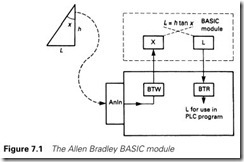
To some extent these features can be provided by specialist modules which can be added to PLCs. Allen Bradley, for example, have a BASIC module (1771-DB) which can be added to a PLC-5 system. This is a small computer which can be programmed in BASIC and can communicate with peripherals (graphics terminals, keyboards, printers, etc.) via RS232 ports, and with data in the PLC via block transfer reads and writes (described in Section 4.4.5). Figure 7.1 shows an example where a mathematical operation is passed to the BASIC module (which acts rather like a maths co-processor). Another common application is to produce printed reports in the absence of a higher level computer.
In general, computers at this level fall into two categories: bus-based systems and industrialized clones of the ubiquitous IBM PC family. The rest of this chapter briefly describes industrial computers belonging to these classes. More detailed information is given in Bus Based Industrial Process Control, and PC Based Instrumentation and Control. Both books are by
M. Tooley and are published by Butterworth-Heinemann.
Bus-based machines
Introduction
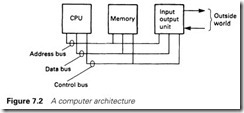
The architecture of any computer (be it PLC, personal computer, mini- computer, games machine or company mainframe) can be represented by Figure 7.2 and consists of a central processor (CPU), memory store and input/output (I/O) linked to the outside world. These are linked by
a bus system (for busbar or omnibus, depending on what source you are first exposed to) which has three components. The data bus carries data between the various elements: I/O to store, store to CPU and so on. The address bus carries the address of the store or I/O port concerned with the data movement, e.g. ‘bring data from I/O port 17 to register C’ or ‘store the contents of register D in store location address hex E147’. The final bus is the control bus. This carries timing and direction signals. This structure allows the idea of an expandable DIY computer to be implemented. The bus is laid out on a printed circuit backplane with established connections for the data, address, and control signals. The designer can then plug in CPU, memory, video and I/O cards to build the computer needed to perform the required task. There are several bus standards, and the commonest are described briefly in Section 7.2.3. The IBM PC clone has this form as well, but the designer has less choice in the
selection of the CPU.
There are actually two uses of the term ‘Bus-based machine’. In the second form a complete master computer is linked to several external devices via a ribbon cable. Data can be read from, or written to, these external instruments. We will first look at the common GPIB (IEEE-488) bus which is of this second type.
IEEE-488 parallel interface bus
This system was originally developed by Hewlett Packard to link HP computers to HP instruments. In its original form it was known as HP-IB (Hewlett Packard Instrumentation Bus). In 1975, the standard was formulated by the American Institute of Electrical and Electronic Engineers as standard IEEE-488 (also popularly known as GP-IB for General Purpose Interface Bus). This allows the linking of up to 15 devices and a computer with a total transmission length of 20 m.
The IEEE-488 bus can support three types of device: listeners, talkers and controllers. Listeners accept data from the bus; typical examples are a printer or a display. Talkers place data, on request, onto the bus; a measuring instrument is a typical talker. A controller assigns the role of any other devices on the bus but only one controller can be active at any one time. The designations listener, talker and controller are attributes of a unit (rather than a description of a unit’s function) and many devices can fill more than one role. A computer, for example, can act as all three.
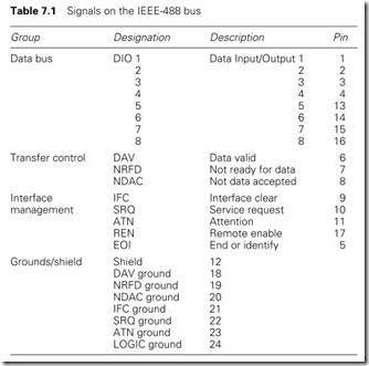
Signals on the bus can be grouped into a bidirectional data bus (which serves the three roles of data transfer, address selection and control selection), transfer control, interface management and grounds/ shields as summarized in Table 7.1.
Signalling is done at TTL levels, with 0 V representing ‘1’ and 3.5 V ‘0’ (the inverse of normal TTL signals). Open collectors are used to
allow the bidirectional data bus and bidirectional control signals (such as NDAC and NFRD) to operate.
The data bus is used for several purposes. It can obviously carry data to one (or more) listeners or data from talkers. It can be used as an address bus to enable or disable one (or more) devices. Up to 15 primary device addresses and 16 secondary addresses can be supported. Normally a secondary address controls an auxiliary function within a primary device. For an analog input device, for example, the channel would be selected with a secondary address, and the input value read with the primary address. Address 31 has a special function, being used to disable all active listeners.
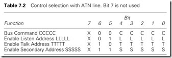
The data bus action is determined by the active controller which uses the ATN line to signal whether the data bus is carrying data or control (address) information. With the ATN line taken low, any active talker is disabled and the new control mode selected as in Table 7.2.
The major attraction of the IEEE-488 bus is its ease of use, with the operation being totally transparent to a programmer working in a high level language. For example, the instruction
OUTPUT 702, Setpoint
sends the data in the variable ‘Setpoint’ in the computer (address 7 represented as 700 and acting as a talker) to the listener with address 02. The actual bus operation corresponding to this instrument has four steps:
1 Deselect all listeners.
2 Select talker (7).
3 Select listener (02).
4 Perform data transfer.
IEEE-488 interface cards are available for many devices, both instru- ments and computers such as IBM PC clones.
Backplane bus systems
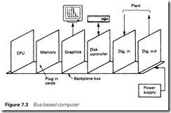
Backplane bus systems are built in the form of Figure 7.3. A backplane provides the data, address and control bus signals, and various cards can be plugged into the bus to configure the system as required.
The advantages of a bus system are obvious: standardization, use of off-the-shelf cards, ease of expansion and a DIY bolt it together yourself approach. Unfortunately each and every microprocessor manufacturer and many equipment manufacturers devised their own standards, with different-sized data words (8 bit, 16 bit or 32 bit), different address ranges and, of course, different edge connectors and pin layouts. Fortunately some common standards do seem to be emerging, notably the VME and STE bus standards.
VME bus is a system designed originally for 16-bit machines and based on an earlier 16-bit bus system known as Versabus. A 24-bit address bus gives a large address range. The introduction of 32-bit microprocessors such as Intel’s 80386 or Motorola’s 68020 led to the upgrade of the VME bus to handle 32-bit data with a second connector. The bus thus exists in 16-bit (single 96-way DIN 41612 connector) or 32-bit (two 96-way connector) forms. In 32-bit form, the address bus was also extended to 32 bit. VME bus cards are generally compatible with either form.
With a high-speed clock (24 MHz data transfer rate), 32-bit data bus and an enormous address range, the VME bus is arguably the most powerful industrial control system available. If speed of performance is
critical it cannot be beaten. It is, however, sophisticated and expensive and, as one user said, ‘You don’t go shopping in a Formula One racing car, you walk, go by bike or take the family estate car’.
In this latter category comes the STE bus (and the PLCs discussed in the rest of this book). The STE bus is an 8-bit data bus system with origins in the earlier STD bus. It has 20 address lines (allowing over 1 Mbyte of memory space) and 4 kbytes of addressable I/O, and has been formalized under the IEEE-1000 standard. This ensures compati- bility between different manufacturers, and has led to it becoming a gen- eral purpose accepted standard where the higher performance of the VME bus is not required.
It has many attractive features. The cards are based on the compact Eurocard size (100 ´ 160 mm) and connections between the cards and the backplane are made by a robust two-part connector (DIN 41612) which is resistant to vibration and shock loads.
STE bus has been designed around an interface between a master processor and a wide range of I/O boards. The microprocessor type is not defined, and any microprocessor can be used providing the interface between the CPU board and the backplane meets the defined standards. The bus can support up to three master CPU boards although, of course, only one of these can be active at any one time. A well-defined procedure is laid down for the selection of control of the bus when contention occurs between the different masters.
IBM PC clones
Up to the early 1980s, the world of personal desktop computers (PCs) was very varied, with a wide range of different machines and no common standard between them. This was matched by a plethora of operating systems, with usually each manufacturer devising its own.
In 1981 the major mainframe manufacturer IBM entered the PC market. The effect of this was dramatic. IBM dominates the commercial computer market, and its timing for entering the PC market was, through design or luck, immaculate. Personal computers were falling in price and had reached a level where their widespread purchase could be justified by most companies. Although the specification for the PC was not particularly noteworthy (and the graphics ability of the early machines was poor), IBM’s reputation ensured that the IBM family of PCs rapidly dominated the market.
IBM chose the software company Microsoft to provide the operating system, known originally as PCDOS. This operating system had a loose relationship to an earlier Z80-based operating system called CP/M. To its credit, IBM was very open about the hardware and software of the PC and designed a bus system which allowed easy expansion. A vast
market of add-on cards appeared, along with cheap IBM clone computers. For these Microsoft provide an operating system identical to PCDOS (for all practical purposes) known as MSDOS.
Since its introduction in 1981 the IBM PC family has undergone a steady development. The original machine, with floppy disk storage and known simply as the IBM PC, was based on the Intel 8088 micro- processor, a 16-bit version of the ubiquitous Intel 8080 (and the Zilog Z80) family. This was followed rapidly in 1982 by the IBM-XT, again an 8088-based machine with hard disk for storage.
The next step occurred in 1984 with the introduction of the IBM-AT. This was based on the more powerful Intel 80286 micro which could handle a large amount of memory (16 Mbyte compared with the 1 Mbyte of the 8088 and 64 kbyte of earlier micros such as the Z80). Unfortu- nately MSDOS (and PCDOS) were designed around 1-Mbyte memories and could not directly use all the memory capability of the 286. The 80286 could also support multitasking where the processor can operate more than one task at a time.
The PC and XT had been constructed with well-documented bus systems allowing the addition of cards such as modems, interface cards, etc. The AT introduced a bus with additional capabilities (which was still compatible with the earlier standard). We will describe these bus systems shortly.
In 1987 IBM introduced a new family, the PS/2 (for Personal System 2) computers with a variety of number suffixes (PS/2-30, PS/2-50, etc.). These are based on a range of Intel processors from the 286 (in the PS/2-30, PS/2-50, PS/2-60), to the 32-bit 80386 (used in the PS/2-55, PS/2-70 and PS/2-80) and 80486 (used in the PS/2-486). These machines also introduced improved graphics facilities and a totally new bus system called MCA (for Micro Channel Architecture).
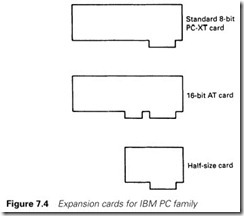
This new bus system was incompatible with the earlier bus standards and has resulted in two divergent systems. The early bus (in the original PC and XT) was based on a 62-way edge connector with an 8-bit data bus and a 19-bit address bus plus control, timing and power supply lines (+12 V, +5 V, 0V and -12 V). The 8-bit data bus was a restriction and IBM increased the data bus to 16 bits in the IBM-AT bus with the addition of an extra 36-pin connector. Both this (and the 62-way connector) use printed circuit board edge con- nectors which are far less robust than the two-part connectors used on STE bus. The two common standards, usually known as the PC bus and AT bus, appear as Figure 7.4 along with smaller half-card formats. These standards are also known as Industry Standard Architecture (or ISA, which has nothing to do with the Instrument Society of America). Although IBM had originated the ISA bus, it never actively pursued legal action against clone and interface board
manufacturers, and a flourishing industry in machines and add-ons developed.
IBM’s approach to the PS/2 MCA bus has, however, been markedly different. The MCA is superior to, but incompatible with, the ISA bus, introducing features such as automatic configuration, higher speed and more tolerance to electrical interference. IBM has protected its rights to the MCA with strict licensing fees and a far less open approach.
Many of the clone manufacturers chose to co-operate against IBM and jointly developed an improved version of ISA called EISA (for Extended Industry Standard Architecture) as an alternative. There are thus four different bus systems for the IBM family: the PC bus, the AT bus, the EISA bus and the MCA. Future developments are not clear at the time of writing, but the ISA bus will be available for the foreseeable future.
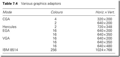
Although the original PC had poor graphics, these have improved through the XT, AT and PS/2, with common standards being shown in Table 7.4. The poor graphics capability of the early IBM PC led to the
development of graphics cards by external manufacturers, such as the monochrome Hercules Graphics Adaptor. These have largely been superseded by the EGA and VGA standards. These latter standards are useful for industrial graphics terminals.
Industrial PCs are based on clones and clone adaptor boards, usually to the AT bus standard. Using serial communications they often act as programming terminals or operator stations with PLCs.
Programming for real time control
The use of conventional programming languages was briefly discussed in Section 1.3.3. Languages such as BASIC, FORTRAN, Pascal and C were designed for general purpose, or scientific, computing and do not normally provide functions for real time control. There are excep- tions, however, with real time variations on the standard language. MACBASIC, for example, is a version of BASIC, with instructions such as AIN(M,N) which gets an analog input from channel N on card M. Most of the single board and bus board computers described earlier operate with non-standard additional instructions to BASIC or C. The Pyramid Integrator, from Allen Bradley, for example, is a rack containing a 5/250 PLC (the top of the PLC-5 family) and a DEC-Vax computer. These communicate via the backplane. The PLC-5/Vax link is designed to be controlled via a program written in C, with additional C instructions (called the Data Table Library) available to access the PLC data table.
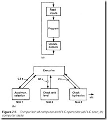
The programmer has to ensure that the computer program responds to plant actions and operator inputs in a reasonable time. One way of achieving this is simply to write a version of the PLC program scan of Figure 7.5 which would have the form
Begin
Repeat
Read Plant Inputs
Work out Required Actions Write Plant Outputs
Until Hellfreezesover End. {of program}
This is possibly satisfactory for small schemes, but could be wasteful of computing time in large schemes because manual operations would expect
a response in under 0.5 s, but the level of water in, say, a large storage tank would only need to be examined perhaps once a minute. Combined in a single scan, activities with widely differing speed requirements would be difficult to manage.
An alternative is to have the required action broken down into a series of tasks which are controlled by a common executive as shown in Figure 7.5(b). The executive can call tasks at different intervals. Task 1, for example, is an automanual changeover run at 0.5-s intervals, task 2 is checking the level in a water tank at 60-s intervals, task 3 is checking the oil level, pressure and filter state in a hydraulic system every 2 s, and so on. This helps to streamline the process by having no wasted time, and aids programming, as each task is totally separate from every other task and can be written independently.
Specialist real time control languages are available, such as ICI’s RTL (for Real Time Language) the US defense language ADA and the CEGB’s CUTLASS (designed initially for power station control).
CUTLASS is a compiled language, originally written for DEC mini- computers, which follows the idea of Figure 7.5(b). A control scheme is broken down into tasks which are activated at preset time intervals. A task program starts with a definition giving its name, priority (in the event of a clash, tasks with highest priority are run first) and its run rate, for example
TASK AUTOSLEW PRIORITY = 236 RUN EVERY 600 ms
Next comes the definition of variables. These can be global (for the whole program and usable in any task) or local to the task. CUTLASS supports the usual forms of reals, integers and booleans (the latter being called logic) but introduces the concept of good and bad data. Any data coming from the outside world have the possibility of being erroneous due to plant failures. In CUTLASS, data can have a value or the state bad. Reals, for example, can have a numeric value or bad. Logic (Boolean) can be true, false, or bad. This state is carried through oper- ations; for example
Aver : = (temp1 + temp2)/2
will yield the average temperature if both temp1 and temp2 are good values, but bad if either temperature reading is faulty. Some operations can produce good outputs with some bad data. A majority vote, for example, of two out of three, will give a good output with one bad value.
A digital input command has the form
DIGIN CARD n m, variable
where n is the card number, m the channel number and variable the name of the variable in the program to which the value is assigned, for example
DIGIN CARD 36 12, StartPB
Digital outputs have the form
DIGOUT variable CARD n m, action 1, action 2, action 3
Here variables n and m have the same meaning, and action 1 is performed if the variable is false, action 2 if it is true and action 3 if it is bad. For example
DIGOUT RUNLAMP CARD 23 7, CLEAR, SET, FLASH
To show the principle, the small code segment below is part of a task controlling auto/manual selection. Variables (whose meaning is obvious from their names) have been previously declared. AutoPermit is a global variable coming in from outside this program segment:
DIGIN CARD 63, 15 AutoSW
AutoReq :=AutoSW AND AutoPermit
AUTOMAN AutoReq {A built in function putting mode to Auto} IF AutoReq=TRUE THEN
AutoLamp=TRUE ELSE
IF AutoPermit=TRUE THEN AutoLamp :=FALSE ELSE
AutoLamp :=BAD ENDIF {Inner IF}
ENDIF {Outer IF}
DIGOUT AutoLamp CARD 14 7 CLEAR, SET, FLASH
Analog inputs are read with a Multiplexed Analog Input (MXANIN) instruction with the form
MXANIN CARD m n, variable1 p, variable2 etc.
where m is the card number, and n, p etc. are the channels. For example
MXANIN CARD 47 1 Setpoint 2, Actual Value
CUTLASS has many built-in control functions such as filters, rate of change, limiters and controllers. We can use the inputs from above as
Error : = (Setpoint – Actual Value) Actuator : = PID (Error, Gain. Ti, Td, Tf)
where PID is a three-term control function, and Gain, Ti and Td are vari- ables holding the settings for the controller and Tf is the high-frequency
roll-off filter. The value in the variable Actuator can be written to the outside world with an ANOUT instruction.
Forth is a language also designed for real time control. Most languages come from academic and research backgrounds. Forth was designed by an astronomer for the control of a telescope at Kitts Peak in the USA. It is an unconventional language in many respects, but once its peculiarities are learned it is ideally suited for industrial use.
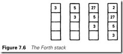
Forth uses the idea of a pushdown stack, which can be considered similar to the spring-loaded piles of plates seen occasionally in cafeterias. As a plate is added, the pile moves down. Numbers in Forth are treated in a similar way; Figure 7.6 shows the numbers 3, 5, 27, 2 being placed in the stack.
Most operations are concerned with numbers at the top of the stack. Polish notation is used, with the arithmetic symbol or operation following the data. The addition 273 + 28 is written
273 28+
and behaves as in Figure 7.7(a). The more involved expression (412 + 27 -16) ´ 3 is written
412 27 + 16 – 3*
and performed as in Figure 7.7(b). In each case we are working with the top pair of digits.
In Forth, the programmer extends the language by defining a series of instructions and giving them a name. For example, we will write a series of instructions to convert a temperature in Fahrenheit to Centigrade. It assumes that the temperature in °F is in the top of the stack and leaves the corresponding temperature in °C on the stack. The definition of a new instruction called FTOC goes
: FTOC {: means this is a definition}
32 {goes to top of stack, pushing ×F down}
– {subtract top of stack from next down} 5*
9/ {×C now on stack}
; {; means end of definition}
We can now write
68 FTOC
and 20 will be left on the stack.
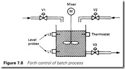
Suppose we want to control the batch process of Figure 7.8, where two chemicals are added to a vat, mixed, heated to some preset tempera- ture, mixed for some time again, and then drained ready for a new batch. We could define a new word BATCH
: BATCH
ADD1 ADD2 MIX1 HEAT MIX2 DRAIN;
These are all new words, with new definitions, for example
: ADD1 OPENV1
BEGIN TESTL1 UNTIL {This is a Forth loop} SHUTV1;
and
: MIX1 MOTOR ON
BEGIN TIME1 UP UNTIL MOTOROFF
Again, new words are introduced (OPENV1, TESTL1) which are again defined until eventually the ‘built-in’ Forth words can be used.
OPENV1 uses standard words:
: OPENV1
1 {state bit 1=‘ON’}
3 {channel number}
5 {card number}
; DIGOUT {standard word in TCS Forth}
;
and TESTL1 is simply
: TESTL1
4 {channel number}
2 {card number}
DIGIN {leaves state 1 or 0 of digital input 4 of card 2 on the stack}
;
Analog inputs and outputs are handled in a similar manner.
When all the user-defined words have been broken down to original Forth words, the sequence is run with the one word BATCH.
Forth programs are perfect examples of top-down programming, where a requirement is split into smaller tasks, which are split into subtasks and so on until units of small size and minimal complexity are created.
Where speed or minimal memory is of absolute importance, the programmer has little choice but to work in machine code. Normally programs are written in assembly code and turned into machine code by an assembler provided by the suppliers of the target computer sys- tem. The resulting program will be compact and fast, but can be difficult to change or maintain if the documentation is not good. The ability to monitor the running program (standard in all PLCs) will not be avail- able unless fault-finding procedures have been written in as part of the specification.
Soft PLCs
Traditionally PLCs have had their own operating systems, written by the supplier and held in the PLC in a Read Only Memory (ROM). This gives the PLC a great deal of security; the software is well proven and cannot be modified, accidentally or intentionally, by the end user. It also provides almost total immunity to the malign influences of computer viruses. The author is almost tempted to say complete immunity, never having heard of a PLC being infected by a virus.
Problems arise, though, when the PLC has to link to computer systems for SCADA systems or to access database or spreadsheet files. This is usu- ally done via serial communications; point to point RS232 at the simplest level, networks such as Ethernet where there is more than one PLC or computer. Allen Bradley did provide a solution for this called the Pyramid Integrator which contained a PLC5 processor and a VAX computer in a common chassis, but it was expensive and has been discontinued.
PLC manufacturers now sell the PLC operating system, and a common solution is to run this on a normal PC. Cards fitted in the PC communicate with the normal PLC plant I/O. This allows easy exchange of data between the ‘PLC’ and the rest of the computer, but does bring some problems which should be seriously considered. First is robustness.
Computers fall over from time to time, usually waiting until the most inconvenient moment as anyone who has used a word-processor will testify. Usually crashes are caused by clashes between software installed on the machine. The system can be made more robust by strictly controlling the software running on the computer and removing all unnecessary program files (e.g. the games and accessories that are normally installed).
The second problem is the power-up time. After a power failure a PLC will normally be working again within a second. A computer, however, can take tens of seconds to come alive and this may be crucial. Some protection can be given by battery backed Uninterruptable Power Supplies (UPS), but in the author’s experience these seem to cause as much trouble as they prevent.
A desktop PC is vulnerable to theft. Even if someone cannot walk out with the PC tucked under their arm, the internal motherboard and memory cards can be stolen and are easily hidden. Even worse, ‘dongles’ are often used to prevent copying of software and a thief, in a hurry, may take the dongles. If a PC based system is left unattended the security of the system should be seriously considered.
Finally, of course, there are computer viruses. These are best con- trolled by restricting access to the computer and running up to date virus detection software. Under no circumstances allow people to use the computer to view their digital camera photos or print out a word processor file from home.
