ELECTRICAL SYSTEM DESCRIPTION
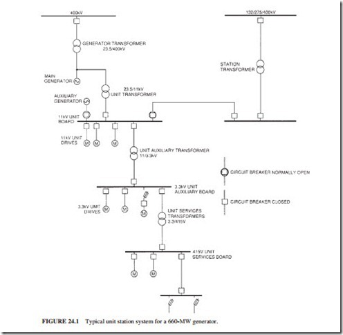
The output voltage of a 660-MW (776-MVA) generator is normally around 23.5 kV. It is connected to the grid via a main output transformer (MOT). The grid voltage varies from 230 to 800 kV. Insulated metal-clad SF6 circuit breakers are used to connect the generator to the grid in modern power plants. The station auxiliary loads should always be supplied with electric power. Figure 24.1 illustrates a typical electrical distribution of a power- generating station.
The Generator Main Output System
Main Generator. The generator is connected to the main output transformer via phase- isolated connections. These connections are air-cooled and rated around 20,000 A for a 660-MW (776-MVA) unit.
Generator Transformers. The generator MOT connects the generator to the grid. It is fitted with on-load tap changers to accommodate the variations in grid voltage. It could be a three-phase unit or a three single-phase unit. It is rated around 800 MVA (for a 776-MVA generator). This rating is based on possible additional 44 MVA from a gas-turbine generator, less than a unit auxiliary load of 20 MVA. The MOT of a 900-MW unit is rated around 1145 MVA. It is normally made of three single-phase transformers, which are fitted with on-load tap changers.
Electrical Auxiliary Systems
The electrical auxiliary systems provide power for the unit auxiliaries. These systems must be designed to prevent a fault including a fire from affecting more than one generating unit. Similarly, a fault on a system that does not have an immediate effect on the operation of the unit should be prevented from propagating into the electrical system and affecting the unit output. This is achieved by segregating the switchgear and cables between the units.
Type of Stations
There are a wide variety of power stations including coal-fired, nuclear, oil-fired, hydraulic, gas turbines, and combined cycles. The following sections describe the different features associated with fossil-fired power stations.
Fossil-Fired Power Stations. The fossil-fired power stations are fueled by coal, oil, or natural gas. The main difference in the electrical auxiliaries between a coal-fired and an oil-fired station is the fuel handling and combustion systems. Figures 24.2 and 24.3 illustrate the electrical auxiliaries system for Littlebrook D oil-fired station.
