Most motors have a lagging power factor because they have coils surrounded by iron. Magnetizing a coil surrounded by iron creates much more inductive reactance than magnetizing a coil alone. The amount of resistance created by inductive reactance is determined by the number of turns of wire and the amount of iron surrounding the coil.
A motor’s power factor can change under certain conditions. If the power factor is given on a motor’s nameplate, it has been calculated with rated voltage, and with rated load applied. A motor’s power factor is lowered if the applied voltage is higher than its nameplate rating or if the motor is underloaded. One or both of these conditions are normal in industry.
Low Power Factor Concerns
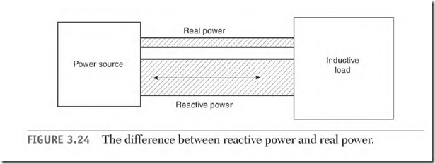
The problem created by a low power factor occurs in the supply lines and the power source. Magnetizing current (reactive or magnetizing amps) is added to the load current (true amperes) value (Fig. 3.24). The result is heat loss and voltage drop in the supply lines. Magnetizing amperes add nothing to the power cost and do no work. However, they do require the same number of circular mils (circular mils were explained in Chapter 1) as the real power amperes.
A transformer large enough to carry a load at unity power factor would overheat if the load’s power factor were too low. A 50 percent power factor requires a transformer two times larger to avoid overheating (with the same load). Power suppliers often charge a penalty if they must provide a larger transformer or if they have to install power factor correcting capacitors. The effect of power factor correcting capacitors is explained later under
Inductive Reactance and Hertz Change
The amount of resistance created by inductive reactance is related to the amount of polarity change (Hz) of the power source. As 1–1z go up, so does the resistance of the inductive circuit. The winding of a motor designed for 50 1-IZ has more resistance on 60-Hz power. With fewer amperes through its winding, the motor has less power than it had with 50 Hz. (As Hz go up, amps go down.)
The power change is proportional to the Hz change. If voltage is increased in the same proportion as the Hz increase, the lost power is restored.
Formula for 50-Hz to 60-Hz Power Change
There are two ways to increase a 50-Hz motor’s power when it is operated on 60 Hz. One is to rewind the motor using fewer turns. The other is to increase the applied voltage. Both methods increase the volts per turn, which increases the amperes. The following formulas are used to increase the applied voltage:
60 = 50 — – 1.095 Increase the voltage 10%
60 + 50 = 1.2 The square root of 1 . 2 = 1.095
1.10 x the 50-Hz voltage — the same horsepower but less torque
60 + 50 – 1.2
1.2 x the 50-Hz voltage — the same torque but more horsepower
The increased horsepower will increase the motor’s heat, but the increase in RPM will increase the motor’s cooling ability. In most cases, the increased cooling compensates for the increased heat.
Impedance in a Three-Phase Winding
There are two forms of resistance to current flow in AC motor windings: resistance of the wire and inductive reactance of the winding. The sum of the resistance and inductive reactance is called impedance.
The following is a hypothetical example of three-phase motor data. It will show the amount of resistance to current flow that inductive reactance has in the total impedance of the motor.
• Hypothetical motor nameplate data: 230 V, 5 A
• Winding data: connection one delta (the delta connection puts each phase across the line).
• Four-pole: three coils per pole group, 25 turns of wire; each turn contains 1 ft of wire. (#17 wire has 5.05 ohms of resistance per 1000 ft.)
• Impedance of one phase of a four-pole three-phase motor is as follows:
Resistance:
3 coils x 25 turns (l ft per turn) = 75 ft per pole group
75 ft x 4 pole groups — 300 ft of 17 wire per phase
300 ft + 1000 ft = 0.3 (multiplier to get resistance of 300 ft)
0.3 x 5.05 ohms – — 1 .515 ohms (resistance of one phase)
Inductive reactance:
230 volts 5 amperes — 46 ohms of impedance per phase
46 ohms (impedance) — 1.515 ohms of resistance![]()
44.48 ohms of inductive reactance
If 230 volts DC are applied to one phase:
Volts + ohms = amps
230 volts + 1.515 ohms = 151.8 amps (through one 17 wire)
1.515 ohms + 46 ohms = 3.2%
Only 3.2 percent of the resistance to current flow is furnished by the resistance of the winding. Inductive reactance furnishes the remaining
96.8 percent of the resistance.
