PNEUMATIC CONTROL COMBINATIONS
GENERAL
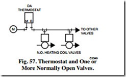
A complete control system requires combinations of several controls. Figure 57 shows a basic control combination of a thermostat and one or more control valves. A normally open control valve assembly is selected when the valve must open if the air supply fails. A normally open control valve requires a direct-acting thermostat in the heating application shown in Figure 56. Cooling applications may use normally closed valves and a direct-acting thermostat. The thermostat in Figure 56 has a 5 degree throttling range (output varies from 3 to 13 psi of the 5 degree range) and the valves have an 8 to 12 psi spring range, then the valve will modulate from open to closed on a 2 degree rise in temperature at the thermostat.
A normally open or a normally closed valve may be combined with a direct-acting or a reverse-acting thermostat, depending on the requirements and the conditions in the controlled space. Applications that require several valves controlled in unison (e.g., multiple hot water radiation units in a large open area) have two constraints:
— All valves that perform the same function must be of the same normal position (all normally open or all normally closed).
— The controller must be located where the condition it measures is uniformly affected by changes in position of the multiple valves. If not, the application requires more than one controller.
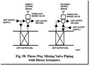
A direct- or reverse-acting signal to a three-way mixing or diverting valve must be selected carefully. Figure 58 shows that the piping configuration determines the signal required.
SEQUENCE CONTROL
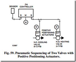
In pneumatic control systems, one controller can operate several dampers or valves or several groups of dampers or valves. For example, year-round air conditioning systems sometimes require heating in the morning and evening and cooling in the afternoon. Figure 59 shows a system in which a single controller controls a normally open heating valve and normally closed cooling valve. The cooling valve is set for an 8 to 13 psi range and the heating valve, for a 2 to 7 psi range. The controller operates the two valves in sequence to hold the temperature at the desired level continually.
When the temperature is so low that the controller calls for full heat, the branchline pressure is less than 3 psi. The normally open heating valve is open and the normally closed cooling valve is closed. As the temperature rises, the branchline pressure increases and the heating valve starts to close. At 7 psi branchline pressure, the heating valve is fully closed. If the temperature continues to rise, the branchline pressure increases until the cooling valve starts to open at 8 psi. The temperature must rise enough to increase the branchline pressure to 13 psi before the cooling valve will be full open. On a drop in temperature, the sequence is reversed.
Valves with positive positioners ensure tight close-off of the heating valve at 7 psi branchline pressure, and delay opening of the cooling valve until 8 psi branchline pressure is reached. Positive positioners prevent overlapping caused by a variation in medium pressure, a binding valve or damper, or a variation in spring tension when using spring ranges for sequencing.
A greater deadband can be set on the positioners to provide a larger span when no energy is consumed. For example, if the positioners are set for 2 to 7 psi on heating and 13 to 18 psi on cooling, no energy is used when the controller branchline pressure is between 7 and 13 psi. The positioners can also be set to overlap (e.g., 4 to 9 and 7 to 12 psi) if required.
Valve and damper actuators without positioners have various spring ranges. To perform the sequencing application in Figure 59 without positioners, select a heating valve actuator that has a 2 to 7 psi spring range and a cooling valve actuator that has an 8 to 13 psi spring range. Although this method lessens precise positioning, it is usually acceptable in systems with lower pressure differentials across the valve or damper and on smaller valves and dampers .
LIMIT CONTROL
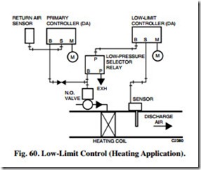
Figure 60 shows a sensor-controller combination for space temperature control with discharge low limit. The discharge low limit controller on a heating system prevents the discharge air temperature from dropping below a desired minimum.
Low-limit control applications typically use a direct-acting primary controller and a normally open control valve. The direct-acting, low-limit controller can lower the branchline pressure regardless of the demands of the room controller, thus opening the valve to prevent the discharge air temperature from dropping below the limit controller setpoint. Whenever the low- limit discharge air sensor takes control, however, the return air sensor will not control. When the low-limit discharge air sensor takes control, the space temperature increases and the return air sensor will be unable to control it.
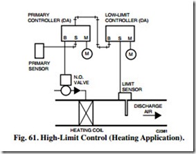
A similar combination can be used for a high-limit heating control system without the selector relay in Figure 61. The limit controller output is piped into the exhaust port of the primary controller, which allows the limit controller to limit the bleed-down of the primary controller branch line.
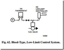
Bleed-type, low-limit controllers can be used with pilot- bleed thermostats (Fig. 62). A restrictor installed between the thermostat and the low-limit controller, allows the low limit controller to bleed the branch line and open the valve. The restrictor allows the limit controller to bleed air from the valve actuator faster than the thermostat can supply it, thus overriding the thermostat.
MANUAL SWITCH CONTROL
Common applications for a diverting switch include on/off/ automatic control for a heating or a cooling valve, open/closed control for a damper, and changeover control for a two-pressure air supply system. Typical applications for a proportional switch include manual positioning, remote control point adjustment, and minimum damper positioning.
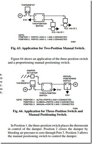
Figure 63 shows an application for the two-position manual switch. In Position 1, the switch places the thermostat in control of Valve 1 and opens Valve 2 by bleeding Valve 2 to zero through Port 1. When turned to Position 2, the switch places the thermostat in control of Valve 2 and Valve 1 opens.
CHANGEOVER CONTROL FOR TWO- PRESSURE SUPPLY SYSTEM
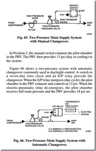
Figure 65 shows a manual switch used for changeover from 13 to 18 psi in the mains. Either heating/cooling or day/night control systems can use this arrangement. In Position 1, the switch supplies main pressure to the pilot chamber in the PRV. The PRV then provides 18 psi (night or heating) main air pressure to the control system.
COMPENSATED CONTROL SYSTEM
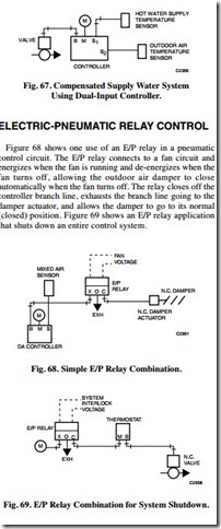
In a typical compensated control system (Fig. 67), a dual- input controller increases or decreases the temperature of the supply water as the outdoor temperature varies. In this application, the dual-input controller resets the water temperature setpoint as a function of the outdoor temperature according to a preset schedule. The system then provides the scheduled water temperature to the convectors, fan-coil units, or other heat exchangers in the system.
PNEUMATIC-ELECTRIC RELAY CONTROL
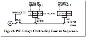
A P/E relay provides the interlock when a pneumatic controller actuates electric equipment. The relays can be set for any desired pressure. Figure 70 shows two P/E relays sequenced to start two fans, one at a time, as the fans are needed.
On a rise in temperature, Relay 1 puts Fan 1 in operation as the thermostat branchline pressure reaches 7 psi. Relay 2 starts Fan 2 when the controller branchline pressure reaches 12 psi. On a decrease in branchline pressure, Relay 2 stops Fan 2 at 10 psi branchline pressure, and Relay 1 stops Fan 1 at 5 psi branchline pressure.
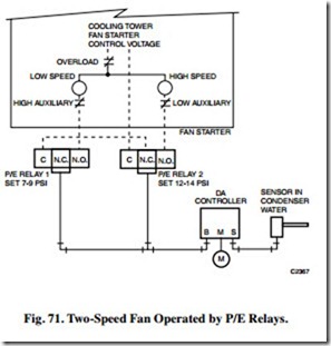
Figure 71 shows two spdt P/E relays starting and stopping a two-speed fan to control condenser water temperature.
Voltage is applied to the common contact of Relay 1 from the normally closed contact of Relay 2. When the controller branchline pressure rises to 9 psi, the cooling tower fan is started on low speed by Relay 1 which makes common to normally open. As a further rise in temperature increases the branchline pressure to 14 psi, Relay 2 breaks the normally closed circuit and makes the normally open circuit, removing voltage from Relay 1, shutting down the low speed, and energizing the high speed. On a decrease in temperature, the sequence reverses and the changes occur at 12 and 7 psi respectively.
PNEUMATIC RECYCLING CONTROL
E/P and P/E relays can combine to perform a variety of logic functions. On a circuit with multiple electrically operated devices, recycling control can start the devices in sequence to prevent the circuit from being overloaded. If power fails, recycling the system from its starting point prevents the circuit overload that could occur if all electric equipment restarts simultaneously when power resumes.
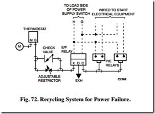
Figure 72 shows a pneumatic-electric system that recycles equipment when power fails.
When power is applied, the E/P relay operates to close the exhaust and connect the thermostat through an adjustable restrictor to the P/E relays. The electrical equipment starts in sequence determined by the P/E relay settings, the adjustable restrictor, and the branchline pressure from the thermostat. The adjustable restrictor provides a gradual buildup of branchline pressure to the P/E relays for an adjustable delay between startups. On power failure, the E/P relay cuts off the thermostat branch line to the two P/E relays and bleeds them off through its exhaust port, shutting down the electrical equipment. The check valve allows the thermostat to shed the controlled loads as rapidly as needed (without the delay imposed by the restrictor).

