ACTUATORS AND FINAL CONTROL ELEMENTS
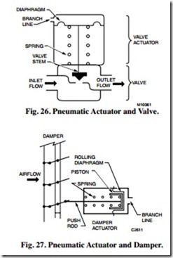
A pneumatic actuator and final control element such as a valve (Fig. 26) or damper (Fig. 27) work together to vary the flow of the medium passing through the valve or damper. In the actuator, a diaphragm and return spring move the damper push rod or valve stem in response to changes in branchline pressure.
ACTUATORS
GENERAL
Pneumatic actuators position damper blades and valve stems. A damper actuator typically mounts on ductwork or on the damper frame and uses a push rod and crank arm to position the damper blades (rotary action). A valve actuator mounts on the valve body and positions the valve stem directly (linear action) for a globe valve or rotary action via linkage for a butterfly valve. Valve actuator strokes typically are between one-quarter and one and one-half inch. Damper actuator strokes range from one to four inches (longer in special applications). In commercial pneumatic actuators, air pressure positions the actuator in one direction and a spring returns it the other direction.
Valve actuators are direct or reverse acting. Damper actuators are direct acting only. A direct-acting actuator extends on an increase in branchline pressure and retracts on a decrease in pressure. A reverse-acting actuator retracts on an increase in branchline pressure and extends on a decrease in pressure.
Pneumatic valve and damper actuator assemblies are termed “normally open” or “normally closed.” The normal position is the one assumed upon zero actuator air pressure. Three-way valves have both normally open (N.O.) and normally closed (N.C.) ports.
SPRING RANGES
Springs used in valve and damper actuators determine the start pressure and pressure change required for full movement of the actuator from open to closed, or from closed to open. Actuators designed for special applications can move through the full range, open to closed or closed to open, on a limited change in pressure from the controller. Such actuators can provide a simple form of sequence control (e.g., operating heating and cooling valves from a single thermostat). Typical spring pressure ranges are 2-7 psi, 8-12 psi, and 3-13 psi.
CONTROL VALVES
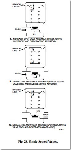
Single-seated globe valves (Fig. 28) are used where tight close-off is required. The valve body can be either direct acting or reverse acting. A direct-acting valve body allows flow with the stem up, while a reverse-acting valve body shuts off flow with the stem up. The combination of valve body and actuator (called the valve assembly) determines the normal valve stem position.
The position maintained by the valve stem depends on the balance of forces acting on it:
— Force F1 from the air pressure on the diaphragm
— Opposing force F2 from the actuator spring
— Controlled-medium force F3 acting on the valve disc and plug due to the difference between inlet and outlet pressures
An increase in controller branchline pressure increases force F1, (Fig. 28A), moving the diaphragm down and positions the valve stem toward closed until it has moved far enough that the sum of the spring force F2 and the controlled-medium force F3 increases balance the increased force F1 on the diaphragm. Conversely, a decrease in controller branchline air pressure in the diaphragm chamber of a direct-acting actuator decreases force F1, allowing forces F2 and F3 to push the diaphragm upward and move the valve stem toward the open position.
In Figure 28B, branchline pressure is applied on the bottom surface of the diaphragm. An increase in air pressure in the diaphragm chamber increases force F1 causing the actuator diaphragm to move upward and open the valve. Motion continues until the increase in pressure on the diaphragm plus the controlled-medium force F3 is balanced by the increase in spring compression (force F2). On a decrease in air pressure in the diaphragm chamber, the compressed spring moves the diaphragm down toward its normal position and the valve stem
toward closed. A normally closed valve assembly usually has a lower close-off rating against the pressure of the controlled medium than a normally open valve because the spring force In Figure 28C, an increase in branchline pressure in the actuator increases force F1 causing the diaphragm to move downward and open the valve. Motion continues until the increase in pressure on the diaphragm (force F1) plus the
controlled-medium force F3 is balanced by the increase in spring compression (force F2). On a decrease in air pressure in the diaphragm chamber, the compressed-spring pressure moves the diaphragm up and the valve stem moves toward the closed position.
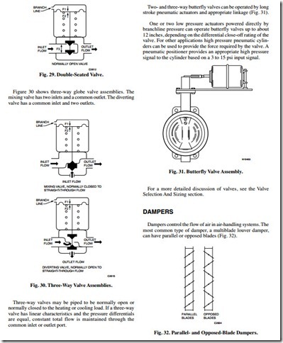
In a double-seated valve (Fig. 29), the controlled agent flows between the two seats. This placement balances the inlet pressures between the two discs of the plug assembly and reduces the actuator force needed to position the plug assembly. Double-seated valves generally do not provide tight close-off because one disc may seat before the other and prevent the other disc from seating tightly.
Two- and three-way butterfly valves can be operated by long stroke pneumatic actuators and appropriate linkage (Fig. 31).
One or two low pressure actuators powered directly by branchline pressure can operate butterfly valves up to about 12 inches, depending on the differential close-off rating of the valve. For other applications high pressure pneumatic cylinders can be used to provide the force required by the valve. A pneumatic positioner provides an appropriate high pressure signal to the cylinder based on a 3 to 15 psi input signal.
Figure 33 shows normally open and normally closed paral- lel-blade dampers. A normally open damper returns to the open position with low air pressure in the actuator diaphragm chamber. An increase in branchline pressure forces the rolling diaphragm piston to move against the spring, and a decrease allows the compressed spring to force the piston and diaphragm back to the normal position. As with valve actuators, intermediate positions depend on a balance between the force of the control air pressure on the diaphragm and the opposing force of the actuator spring.
A normally closed damper returns to the closed position with low air pressure in the actuator diaphragm chamber. The way the damper blades, crank arm, and push rod are oriented during installation determines the normal (open or closed) position of the damper blades.
For a more detailed discussion of dampers, see the Damper Selection and Sizing section.


