CONDITION MONITORING
Various condition monitors are installed on generators and protective systems to identify fault conditions early and to take corrective action to prevent a major failure.
Temperature Monitoring—Thermocouples
Thermocouples are installed in the generator system at the following locations:
● The inlet and the outlet of the hydrogen flow to the heat exchanger
● The inlet and the outlet of the stator water flow to the heat exchanger
● The stator core temperatures
● Hydrogen seal face temperatures
The thermocouple readings provide critical information about the generator. For example, an increase in the stator water temperature at the outlet of the heat exchanger is indicative of a possible blockage in the water channels of the stator bars. Note that the change in the read- ing of the thermocouple occurs around 30 min after the fault has occurred. This is so because of the delay associated with the conduction of heat from the hot spot to the thermocouple.
Direct measurement of the rotor conductor bar (winding) temperature is not possible. However, the average rotor bar temperature can be deduced from an ohmmeter connected to the rotor current and the voltage across the slip rings.
Hydrogen Gas Analysis
Gaseous products and liquid aerosol are produced at the surface of an organic insulation when its temperature exceeds 200°C. These products become entrained with the hydrogen gas inside the generator when there is an insulation fault. There are two types of instruments used to detect these products online. They rely on analyzing either the gases or the particulates generated when the fault occurs.
A fault that originates in the stator core is called a core fault. It normally results in the melting of a large number of core laminations. There is no protection scheme to isolate the generator when this fault occurs. It is only detected when a ground fault occurs due to failure of the insulation between the stator winding and the core.
An incipient core fault is a defect that causes shorts between the stator laminations. It can be caused by a scratch or metallic debris. It may be discovered during flux tests or if it is in the vicinity of a thermocouple. It does not normally cause an outage because its damage is limited. However, it can grow during operation to cause a major core fault. Its growth will most likely be caused by pole slipping. This is a condition that occurs due to either insta- bility or a decay in the rotor flux under decreased excitation.
Studies have shown that the interlamination insulation will break down under these conditions, resulting in growth of the damaged area. It is of utmost importance to keep the generator area clean when it is opened up for maintenance. Any foreign material left in the air gap can damage the laminations and cause a failure.
The ion-chamber particle detector, also known as a core monitor, is used to detect stator winding faults caused by thermal degradation of the insulation. These faults were detected in the past when the insulation failed, causing an interwinding or a ground fault. The hydrogen coolant enters a chamber in this equipment lined with either thorium oxide or americium pellets. The lining ionizes some of the hydrogen molecules by emitting alpha particles. The ionized molecules then pass between electrodes maintained at a specified voltage difference. The free ions are collected at the electrodes, causing a small electric current to be produced in a circuit.
When aerosol enters the chamber, the current generated by the ions decreases. Thus, a reduction in the current indicates insulation degradation. Oil mist entrained with the hydro- gen also causes a deflection in the current reading and an alarm.
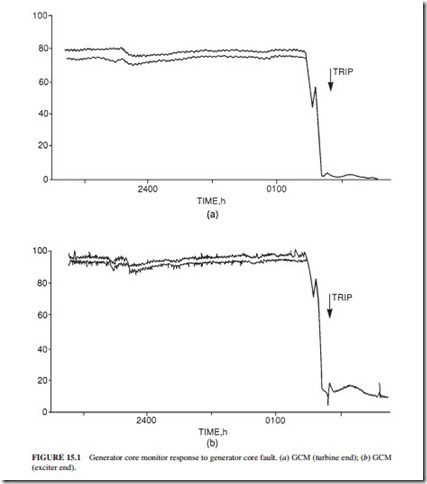
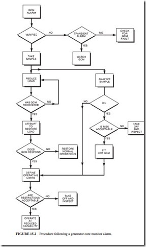
Figure 15.1 illustrates the response of a generator core monitor (GCM) to a core fault. Figure 15.2 shows the procedure that should be followed upon receiving an alarm from a GCM.
Hydrogen Dew Point Monitoring and Control
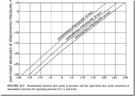
It is important to control the concentration of moisture in hydrogen to prevent arcing in the generator and aqueous stress-corrosion cracking in the end rings. The objective of the moisture control is to prevent condensation inside the generator. Table 15.1 provides a summary of the dew point requirements for hydrogen-cooled generators under various conditions. The hydrogen driers will normally be able to maintain the required dew point during normal operation unless the concentration of moisture in oil exceeds the specified limit. Also note that the dew point increases with the pressure, as shown in Fig. 15.3. For example, a dew point of -20°C at atmospheric pressure corresponds to a dew point of -4.5°C at 3 bar (gauge). It is recommended to use the dew point at operating pressure to avoid confusion.
The effect of condensation on the insulation of a large generator depends on the type and condition of the insulation system. Epoxy-bonded insulation systems have high resistance to moisture. However, if delamination has occurred in mica insulation, moisture could penetrate deeply into the insulation system. If water has penetrated into the insulation during an outage, the dielectric strength will drop significantly. A dryout is necessary under these con- ditions before returning the unit to service, to prevent a possible ground fault. It consists of replacing the moist gas in the generator with dry gas and recirculating it until the insulation becomes dry. Dryout techniques that rely on heating the conductors will not remove the moisture. They only move the moisture to the surface. Blowing heated air on the windings will cause additional condensation on the windings, thereby worsening the situation.
Vibration Monitoring
The turbine supervisory system monitors the vibration and other parameters of the turbines and the generator. Vibration transducers normally measure the velocities of the bearing pedestals.
The corresponding levels of displacement are displayed and recorded. Alarms provide warning at a specified vibration amplitude. The unit is also tripped at a higher vibration amplitude to pre- vent damage to the turbines, connecting pipework, and bearings. Additional diagnostic equip- ment is normally installed at the bearing pedestals to monitor the vibration amplitude and phase.
The vibration readings are recorded during start-up and shutdown. They provide the sig- nature of the turbine-generator over a wide range of frequencies. The phase and amplitude of these data are analyzed to identify if the vibration was caused by a mechanical imbalance, misalignment, oil whirl, or bent shaft. Thermal imbalances are also detected, and the rotor is balanced before returning the unit to service.


