RUN-UP AND STABLE OPERATING REGIONS
In addition to having suYcient torque to start the load it is obviously necessary for the motor to bring the load up to full speed. To predict how the speed will rise after switching on we need the torque–speed curves of the motor and the load, and the total inertia.
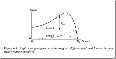
By way of example, we can look at the case of a motor with two diVerent loads (see Figure 6.5) . The solid line is the torque–speed curve of the motor, while the dotted lines represent two diVerent load characteristics. Load (A) is typical of a simple hoist, which applies constant torque to the motor at all speeds, while load (B) might represent a fan. For the sake of simplicity, we will assume that the load inertias (as seen at the motor shaft) are the same.
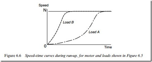
The speed–time curves for run-up are shown in Figure 6.6. Note that the gradient of the speed–time curve (i.e. the acceleration) is obtained by dividing the accelerating torque Tacc (which is the diVerence between the torque developed by the motor and the torque required to run the load at that speed) by the total inertia.
In this example, both loads ultimately reach the same steady speed, N (i.e. the speed at which motor torque equals load torque), but B reaches full speed much more quickly because the accelerating torque is higher during most of the run-up. Load A picks up speed slowly at Wrst, but then accelerates hard (often with a characteristic ‘whoosh’ produced by the ventilating fan) as it passes through the peak torque–speed and approaches equilibrium conditions.
It should be clear that the higher the total inertia, the slower the acceleration and vice versa. The total inertia means the inertia as seen at the motor shaft, so if gearboxes or belts are employed the inertia must be ‘referred’ as discussed in Chapter 11.
An important qualiWcation ought to be mentioned in the context of the motor torque–speed curves shown by the solid line in Figure 6.5. This is that curves like this represent the torque developed by the motor when it has settled down at the speed in question, i.e. they are the true steady-state curves. In reality, a motor will generally only be in a steady- state condition when it settles at its normal running speed, so for most of the speed range the motor will be accelerating. In particular, when the motor is Wrst switched on, there will be a transient period of a few cycles as the three currents gradually move towards a balanced 3-phase pat- tern. During this period the torque can Xuctuate wildly and the motor can pick up signiWcant speed, so the actual torque may be very diVerent from that shown by the steady-state curve, and as a result the instantaneous speeds can Xuctuate about the mean value. Fortunately, the average torque during run-up can be fairly reliably obtained from the steady-state curves, particularly if the inertia is high and the motor takes many cycles to reach full speed, in which case we would consider the torque–speed curve as being ‘quasi-steady state’.
Harmonic effects – skewing
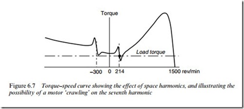
A further cautionary note in connection with the torque–speed curves shown in this and most other books relate to the eVects of harmonic air- gap Welds. In Chapter 5, it was explained that despite the limitations imposed by slotting, the stator winding magnetic Xux (MMF) is remark- ably close to the ideal of a pure sinusoid. Unfortunately, because it is not a perfect sinusoid, Fourier analysis reveals that in addition to the predom- inant fundamental component, there are always additional unwanted ‘space harmonic’ Welds. These harmonic Welds have synchronous speeds that are inversely proportional to their order. For example a 4-pole, 50 Hz motor will have a main Weld rotating at 1500 rev/min, but in addition there may be a Wfth harmonic (20-pole) Weld rotating in the reverse direction at 300 rev/min, a seventh harmonic (28-pole) Weld ro- tating forwards at 214 rev/min, etc. These space harmonics are minimised by stator winding design, but can seldom be eliminated.
If the rotor has a very large number of bars it will react to the harmonic Weld in much the same way as to the fundamental, producing additional induction motor torques centred on the synchronous speed of the harmonic, and leading to unwanted dips in the torque speed, typic- ally as shown in Figure 6.7.
Users should not be too alarmed as in most cases the motor will ride through the harmonic during acceleration, but in extreme cases a motor might, for example, stabilise on the seventh harmonic, and ‘crawl’ at about 214 rev/min, rather than running up to 4-pole speed (1500 rev/ min at 50 Hz), as shown by the dot in Figure 6.7.
To minimise the undesirable eVects of space harmonics the rotor bars in the majority of induction motors are not parallel to the axis of rotation, but instead they are skewed (typically by around one or two slot pitches) along the rotor length. This has very little eVect as far as the fundamental Weld is concerned, but can greatly reduce the response of the rotor to harmonic Welds.
Because the overall inXuence of the harmonics on the steady-state curve is barely noticeable, and their presence might worry users, they are rarely shown, the accepted custom being that ‘the’ torque–speed curve represents the behaviour due to the fundamental component only.
High inertia loads – overheating
Apart from accelerating slowly, high inertia loads pose a particular problem of rotor heating, which can easily be overlooked by the unwary user. Every time an induction motor is started from rest and brought up to speed, the total energy dissipated as heat in the motor windings is equal to the stored kinetic energy of the motor plus load. (This matter is explored further via the equivalent circuit in Chapter 7.) Hence with high inertia loads, very large amounts of energy are released as heat in the windings during run-up, even if the load torque is negligible when the motor is up to speed. With totally enclosed motors the heat ultimately has to Wnd its way to the Wnned outer casing of the motor, which is cooled by air from the shaft-mounted external fan. Cooling of the rotor is therefore usually much worse than the stator, and the rotor is thus most likely to overheat during high inertia run-ups.
No hard and fast rules can be laid down, but manufacturers usually work to standards which specify how many starts per hour can be tolerated. Actually, this information is useless unless coupled with reference to the total inertia, since doubling the inertia makes the problem twice as bad. However, it is usually assumed that the total inertia is not likely to be more than twice the motor inertia, and this is certainly the case for most loads. If in doubt, the user should consult the manufacturer who may recommend a larger motor than might seem necessary simply to supply the full-load power requirements.
Steady-state rotor losses and efficiency
The discussion above is a special case, which highlights one of the less attractive features of induction machines. This is that it is never possible for all the power crossing the air-gap from the stator to be converted to mechanical output, because some is always lost as heat in the rotor
circuit resistance. In fact, it turns out that at slip s the total power (Pr) crossing the air-gap always divides so that a fraction sPr is lost as heat, while the remainder (1 – s)Pr is converted to useful mechanical output (see also Chapter 7.).
Hence, when the motor is operating in the steady state the energy conversion eYciency of the rotor is given by
This result is very important, and shows us immediately why operating at small values of slip is desirable. With a slip of 5% (or 0.05), for example, 95% of the air-gap power is put to good use. But if the motor was run at half the synchronous speed (s ¼ 0.5), 50% of the air- gap power would be wasted as heat in the rotor.
We can also see that the overall eYciency of the motor must always be signiWcantly less than (1-s), because in addition to the rotor copper losses there are stator copper losses, iron losses and windage and friction losses. This fact is sometimes forgotten, leading to conXicting claims such as ‘full-load slip = 5%, overall eYciency =96%’, which is clearly impossible.
Steady-state stability – pullout torque and stalling
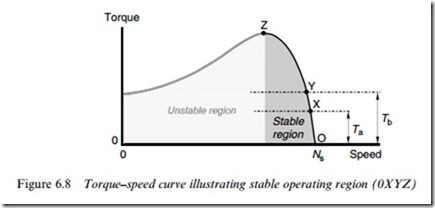
We can check stability by asking what happens if the load torque suddenly changes for some reason. The load torque shown by the dotted line in Figure 6.8 is stable at speed X, for example: if the load torque increased from Ta to Tb, the load torque would be greater than the motor torque, so the motor torque would decelerate. As the speed dropped, the motor torque would rise, until a new equilibrium was reached, at the slightly
lower speed (Y). The converse would happen if the load torque were reduced, leading to a higher stable running speed.
But what happens if the load torque is increased more and more? We can see that as the load torque increases, beginning at point X, we eventually reach point Z, at which the motor develops its maximum torque. Quite apart from the fact that the motor is now well into its overload region, and will be in danger of overheating, it has also reached the limit of stable operation. If the load torque is further increased, the speed falls (because the load torque is more than the motor torque), and as it does so the shortfall between motor torque and load torque be- comes greater and greater. The speed therefore falls faster and faster, and the motor is said to be ‘stalling’. With loads such as machine tools (a drilling machine, for example), as soon as the maximum or ‘pullout’ torque is exceeded, the motor rapidly comes to a halt, making an angry humming sound. With a hoist, however, the excess load would cause the rotor to be accelerated in the reverse direction, unless it was prevented from doing so by a mechanical brake.


