Cable Tray Types
Light Duty Cable Tray
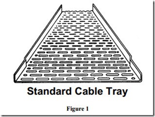
Standard cable tray is suitable for light and medium duty installation work. It is particularly useful for sheathed cables which can be easily dressed and secured to the tray using the numerous perforations. These perforations also provide ventilation to cool the cables.
Medium Duty Cable Tray
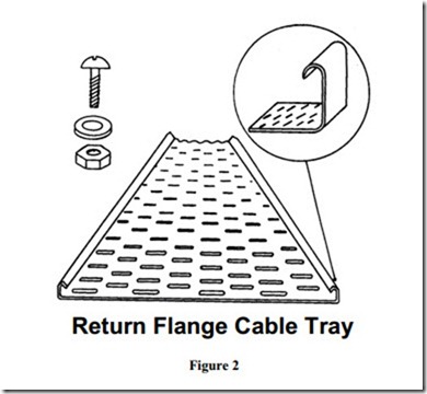
The design of return flange cable tray differs from the standard type in that the flange has a turned edge, see Figure 2. This makes the tray several times stronger than the standard tray, yet it remains light and easy to install. The flange height is 25mm with a 6mm return.
Return flange cable tray uses patented snap-on couplers which fit over the outside of the tray flanges and are secured by round headed bolts. The heads of the bolts should be inside the tray to prevent damage to the cables
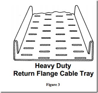
Heavy duty cable tray is designed for use in circumstances where high loading or adverse site conditions are experienced. The heavy duty perforation pattern combined with a wide return flange ensures that the tray is rigid and strong. See Figure 3. Patented coupling systems which are convenient to use are usually available.
Cable Tray Accessories
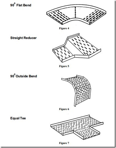
A range of factory made accessories is readily available. A selection of these accessories is illustrated in Figures 4, 5, 6 and 7.
When installing cable tray it is essential that the tray is well supported and securely fixed. It is possible to complete a cabletray installation by making use of the wide range of factory made accessories. However, it may be necessary to fabricate joints, bends, tees etc., to meet particular installation requirements.
Most types of cable tray jointing involves the use of nuts and bolts. A round head bolt should be used and these bolts should be installed with the head placed inside the tray. This reduces the risk of damage to cables being drawn along the tray.
Cable tray systems have a number of advantages over other types of wiring systems. Some of these advantages are listed below:
· Ease of installation
· Economy of time and materials
· Facility for extending the system to take additional cables
· Position and availability of supports
The type and size of cable tray selected will depend on such factors as environmental conditions, the size and type of cables being installed and any requirement for future extension of the system.
Protecting Cut Edges
Where a tray has been cut, the steel edges must be protected from corrosion by sealing them with zinc rich paint in the case of galvanised tray. An appropriate primer must be used for painted tray and a liquid plastic solution for plastic coated tray.
Site-applied protection cannot normally match the protection qualities of the original factory applied finish. However, the absence of site applied protection can seriously reduce the effectiveness of the original finish and result in corrosion spreading from the point where the tray was cut.
Site-applied protection should be applied as soon as practicable after the tray is cut.
Fitting and Fixing Cable Tray
Cable tray is fixed to building surfaces using three basic methods:
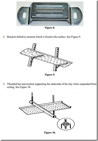
1. Brackets fixed directly to the surface with screws or bolts as required. See Figure 8.
It is essential that all supports are securely fixed. The most appropriate method will be determined by assessing the following points:
· The number and size of the cables being installed
· Is the tray to be fixed flat along a wall or ceiling
· Is the tray to be fixed horizontally along a wall
· Is the tray to be suspended below a ceiling
Earthing of Metallic Cable Tray
Metallic cable tray is an exposed conductive part and must be earthed. All tray joints must be mechanically and electrically sound to ensure continuity throughout its length. Any break in the run of tray must be bridged over by a suitable conductor to maintain the continuity of the earth path. All bolts must be tightened securely using a screwdriver and spanner.
Use of Hand Tools
Figure 11 shows an adjustable spanner. This is used to tighten the nuts on bolts for joining cable tray. It is also used to install hexagonal, cable glands. A pipe grip should not be used on cable glands as it damages the brass or plastic surface. Damaged glands are a sign of bad workmanship.
