Motor Testing
The purpose of testing motors is primarily to make sure that they have been properly constructed, that they meet the manufacturer’s guarantee, and that they will perform their assigned duty with safety under normal conditions of operation. Although the tests herein described deal principally with de machines, they may, with certain modifications, be applied to ac machines as well.
The nature of the various tests and their functions are substantially as follows:
1. To ascertain that the machine complies with the specifications under which it was constructed.
2. To determine whether the machine is suitable for a given duty.
3. To determine the maximum capacity of the machine as limited by considerations of safety and liability to undue deterioriation.
4. To determine the characteristics of the machine so that it may be known in advance how it will perform under given conditions.
5. To facilitate the location of trouble and to familiarize the operator with the characteristics of the machine.
Such tests as applied to commutating machines may be grouped and classified according to the nature of the test in the following manner:
1. Preliminary inspection and adjustment,
2. Resistance measurements,
3. Characteristics,
4. Efficiency,
5. Heating,
6. Miscellaneous.
INSTRUMENTS
Prior to making a test, it is important that the necessary and correct instruments and accessories are available, in addition to the proper source of power. The instrument used depends on the nature of the test to be made. Instruments and accessories most commonly used are tachometers, frequency indicators, meggers, megohmmeters, ohm meters, voltmeters, ammeters, shunts, graphic recording instruments, wattmeters, temperature meters, potential transformers, current trans formers, etc.
Some of the precautions necessary when using instruments are as follows:
1. . Electrical instruments should not be used if the date on the calibration card is over two weeks old.
2. The zero position of an instrument in use should be checked at least twice a day.
3. No instruments should be used which are not suitable for the work.
4. No readings should be taken at scale points below which there is a black or colored band.
5. Instruments should always be tested for stray fields.
6. Any portable instruments having switches should not be left continually in the circuit.
7. Voltmeters must not be left connected to inductive circuits.
8. A special switch for the purpose of disconnecting the voltmeter and table from the field of a synchronous motor when starting should always be used.
9. The voltmeter should be disconnected from the field of a synchronous converter before starting.
1 0 . No field circuit should be opened while a voltmeter is connected across it.
1 1 . Frequency meters should never be placed in a circuit until the voltage has been measured by a voltmeter, and no frequency meter or any other meter should be used on a circuit of higher voltage than the rated voltage of the instrument.
1 2 . The residual voltage of a machine should never be used to operate a frequency meter.
1 3 . Instruments should not be left lying around where they are unprotected or subject to injury.
WIRING
The power for testing is usually delivered through properly protected switchboards, and all precautions should be observed with regard to the safety of attendants, instruments, and machinery associated with the work. This is particularly important when dealing with high-voltage sources of power. A wire misplaced during a test, a wrong switch thrown, or any other careless action may result in very serious con sequences to attendants or to the apparatus. Therefore, it is necessary to know the nature and wiring of a circuit before any switch or instrument manipulation takes place. It is particularly important to see that all cables and terminals are properly insulated, especially those carrying injurious voltages.
MACHINE INSPECTION
A careful inspection of the machine should be made prior to any test, and every point connected to the field, armature, commutator, brushes, brush rigging, terminal block, etc., should be noted to see that it conforms with the manufacturer’s specifications. In addition, the gen eral form of the field frame, the number of field coils and poles (main and interpoles), and the method used to connect the terminals of the windings of one field coil to another should be noted. The number of terminals on each coil will indicate the form of field winding-that is, whether series, shunt, or compound.
For a compound machine, it should be noted whether the two windings are separate or whether one is over the other, noting which one is on the outside. The method of ventilation, whether it involves open or enclosed frames and the use of fans, should be observed. Armature winding construction should be noted, whether it is lap or Jave, and it should be noted whether the conductors are wound directly on the armature core or embedded in slots.
The commutator segments should be counted and the method of securing the armature winding to them noted-that is, whether they are clamped, screwed, or soldered to the commutator segments. The type and number of brushes should be noted, together with the mechanical features and method of securing the rocker arm.
When preparing commutating machines for test, the brushes must be equally spaced around the commutator, 180 electrical degrees apart. The brushes on the stud must align properly with each other and with the commutator bars from the front to the back end of the commutator.
To space the brushes, place a strip of power tape around the commutator and mark the paper where the ends overlap. Remove the paper tape and divide it with a scale or dividers into as many equal divisions as there are poles on the machine. Then replace the paper around the commuta tor and place the overlapping ends together. Space the brushes by the marks on the paper, taking care that the holders are clamped to the stud in the proper position. In some cases, brushes are run trailing and in other cases leading, with reference to the direction of rotation. Radial brushes are also sometimes used. See Fig. 1.
When the brushes have been set, fit them to the commutator surface, using a strip of sandpaper between the commutator and the brush surface. Coarse sandpaper should be used first to obtain an approximate fit, followed with very fine sandpaper for a finish. A close and accurate fit on the commutator is essential to obtain good commutation results. When sandpapering, the sandpaper must be held close to the commu tator to prevent rounding the tip of the brush when drawing the paper away. Sometimes the best results can be obtained by drawing the sandpaper in the direction of rotation, while at other times the best results can be obtained by drawing the sandpaper in the direction opposite to rotation.
When the sandpapering of the brushes is finished, the resulting carbon dust must be blown from the armature, or rotating part. The air blast should be directed away from the rotating part so that the carbon dust is carried completely away and cannot sift into the winding.
The following are some of the more common defects which may appear in motors with commutators:
1. Copper bridges formed between the bars over the side mica of the commutator due to improper turning.
2. Bent end conductors of commutator leads.
3. Improper brush staggering.
4. Improper alignment of brushes with commutator bars.
5. Damaged insulation of armature and field coils.
6. Broken insulation boards on fields.
1. Insufficient clearance between bare electrical terminals or con ductors and ground.
2. Poor joints between electrical conductors.
3. Loose terminals, bus rings, or other connections improperly supported.
4. Brush pigtails too long or touching the armature risers.
5. Insufficient clearance between a brush stud or various parts of fittings and ground.
6. Incorrect brush spring pressure and defective spacing of collector ring taps.
The manufacturer’s nameplate furnishes additional information as to the rating of the machine, terminal voltage, current at full load, type of winding, revolutions per minute of the armature, etc.
LUBRICATION
All machine bearings should be provided with oil wells of sufficient capacity. When oil-ring lubrication is used, the lubricating oil must not be allowed to fall to a level so low in the oil well that the ring does not dip into it. For high bearing pressures, or high speed, some form of forced lubrication is used. The oil is forced into the bearing, either on the bottom or the lower quarter, and enters the bearing at a point in such a way that the revolving shaft draws the oil under the shaft.
Oil from forced lubricated bearings is usually returned to an external cooling tank, where its temperature is reduced before it is pumped back into the bearing. Oil rings and forced lubrication are occasionally used on the same bearings, so that if the oil pressure fails, the rings will supply enough oil to prevent danger until the oil pressure can be restored.
A properly designed bearing may run hot from the following causes: oil ring sticking, scarcity or poor quality of lubricating oil, excessive local pressure in the bearings, insufficient relief on the sides of the bearing, improper alignment and excessive belt pull, or current flowing from the shaft to the frame. The remedy for the greater part of these troubles is obvious. In the case of excessive local pressure in the bearing, or insufficient relief on the sides, the remedy is to remove the high spots of the babbitt or bearing metal with a scraper, and increase the side clearance.
Before starting a machine, all bearings must be filled with the proper amount of oil. Bearings which contain gauge glasses should be filled until the glass is about two-thirds full. Bearings containing an overflow cup gauge should be filled until the oil is about 1/2 inch ( 12.7 mm) from the top of the gauge. Bearings should be carefully filled, and no oil should be spilled on the housing or shell, or upon other parts associated with the bearing, because a false impression may be obtained as to oil leakage or throwing when under test.
To give the bearing a critical test for oil leaking or throwing, the dividing line between the cap and bearing pedestal and between bearing brackets should be painted with whiting. The end of the commutator or field spider adjacent to the bearing should also be given a white coating, so that it is possible, after a comparatively short run, to detect the slightest leakage or throwing of oil.
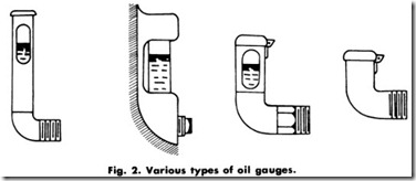
Bearings with the end of the shell visible should be filled with oil until it touches the lower part of the shell at the end of the bearing housing. Overflow gauges (Fig. 2) used on small machines should be filled to within 1I 16th inch ( 1.59 mm) of the overflow. In filling the bearings, a funnel must be used and the oil inserted into the sight holes for the oil rings or through the opening above the shaft at the end of the bearing housing.
During test, no oil should be allowed to leak or be thrown from the bearings upon the rotating parts or windings. This is especially true with reference to commutating machines, where it is important that lubri cating oil be kept away from the commutator, brushes, and fittings. Should oil leaking or throwing on these parts be detected during the test, the test should be immediately discontinued and the cause of leakage removed. If bearings under test rise 40°C ( 104°F) above room temper ature, the fact should be referred to the engineer in charge of the test, for no properly designed bearing should rise more than 40°C (104°F) under normal conditions.
RESISTANCE MEASUREMENTS
The various resistance tests made on commutating machines may be classified as follows:
1. . Armature resistance,
2. Tests for location of defects,
3. Field- winding resistance,
4. Insulation resistance,
5. Dielectric strength.
Armature Resistance
Armature resistance includes not only the resistance of the armature itself, but also the resistance of the brushes and brush contacts-that is, the total resistance of the armature circuit from terminal to terminal. This resistance is nearly always measured by passing a known current through the stationary armature and measuring the voltage drop between the brushes and also across the terminals of the machine. Noting the current flow and the voltage drop, it is a simple matter to calculate the resistance of the various parts of the circuit.
It should be noted that the brush-contact resistance is not constant, but is varying approximately in inverse proportion to the current, from which it follows that the voltage drop of any brush is approximately constant regardless of the load. The brush-contact drop is approximately one volt for carbon, 0.75 volt for graphite and 0.10 volt or less for copper brushes.
Since any resistance will increase with the temperature, the value obtained with the armature cold will be considerably lower than that obtained with the armature hot. Thus, the resistance value obtained during the test will be only approximately correct.
A simplified method of obtaining armature resistance is to pass a current through the armature and also through a standard resistance of approximately the same value and current -carrying capacity, or to compare the drop of potential across each, in which case the current need not be measured.
Test for Locating Defects
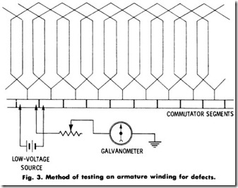
De windings may be tested for grounds, short circuits, high resistance joints, wrong connections, wrong polarity, etc. If a low-resistance ground in armatures with commutators has developed, it may quickly and accurately be located by the following method: A low-voltage current, which is sufficient to give a readable deflection on a galvan ometer or millivoltmeter, is passed through the armature windings from one commutator bar to the next, as shown in Fig. 3. A line is connected from the galvanometer to the ground, and the other galvanometer connection is placed on one of the commutator bars. The supply and galvanometer leads are then passed from segment to segment. If a full deflection is obtained, the coil is grounded.
Measuring the ohmic resistance of the winding will sometimes reveal a wrong connection, which, on a bar-to-bar measurement, would give a uniform deflection all around the commutator. Series or wave windings may sometimes have all conductors joined in series but in the wrong order, making the armature inoperative. In case of multiple or lap windings, double, triple, or even quadruple-spiral re-entrant windings are possible, whereas a single spiral is required. In taking a resistance measurement of the armature, see that the measurement is made from the proper commutator segments.
Special clips are attached to the commutator bars, and are spaced the number of bars apart equal to the total number of bars divided by the number of poles. Each alternate clip is connected in parallel to one terminal of a double bridge, and the remaining clips are connected in parallel and to the other terminal of the double bridge. The resistance reading then obtained is the true running resistance.
Ac windings are similarly tested for grounds, short circuits, open circuits, wrong connections, polarity, etc. In testing for grounds, the methods and apparatus used are similar to those used to de machines, except that with ac, the voltage generated is usually higher. Conse quently, the testing voltages are correspondingly higher, and greater care must be taken in testing. Place the testing equipment as near to the apparatus as possible, as the additional capacitance of the testing lines may raise the voltage at the receiving end much higher than that at the operating end. Unless this precaution is taken, excessive voltage may be applied which may damage the insulation.
If a ground develops, a resistance measurement will generally locate the point at which it occurs, unless each phase has two or more multiple circuits. In this case, it may be more readily located by opening one or more of the end-connection joints and separating the circuits.
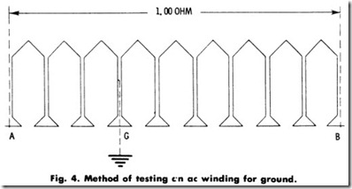
A measurement may be taken as shown in Fig. 4, which represents a single circuit or phase of an AC machine with the ground as indicated. If the resistance between A and B is one ohm, between A and G is 0.35 ohm, and between B and G is 0.65 ohm, the location of the ground is 0.35 of the distance between A and B, from A. Since ten coils are in the circuit, the measurements show that the fourth coil, counting from A, is grounded.
In the case of an ac winding, the ohmic resistance measurement will not always detect a wrong connection, such as a reversed coil, pole section, or phase. Although the copper resistance would be measured correctly, the total winding might be partly reversed, and therefore inoperative. Such faults can be discovered by a polarity or impedance test with alternating current. For this purpose, a single-phase current can be used, since a reading may be taken on the different circuits or between pairs of terminals successively, by shifting the testing lines until all windings have been tested.
Series-Winding Resistance
Since this resistance is of a very low value, special galvanometer measuring sets are generally used. A considerable percentage of the resistance of a series field may consist of contact resistance between the spools.
Shunt-Winding Resistance
This resistance is generally determined by passing a known current through the coils and measuring the drop of potential across the field terminals. With a given current flowing through the field, the voltage drop across any one coil of a de machine should never be more than 5% higher or lower than the average drop.
Insulation Resistance
This test gives an indication of the condition of the insulation of the machine. The actual value of the resistance varies greatly in different apparatus, depending on the type, size, voltage rating, etc. The princi pal worth of such measurements, therefore, is in the relative values of insulation resistance that are even slightly higher than for the good material. Surface dirt or moisture that causes loss of insulation resis tance may also cause low dielectric strength.
Insulation resistances will vary inversely with the temperature-that is, the insulation resistance will decrease with an increase in tempera ture. As an approximation, the insulation resistance will be halved by an 8° to l0°C rise in temperature of the apparatus. As an example, when new insulation or insulation that is very damp is being dried, the resistance will generally fall rapidly as the temperature is raised to a drying value. After falling to the minimum for a given temperature, the resistance will rise as moisture is expelled from the insulation.
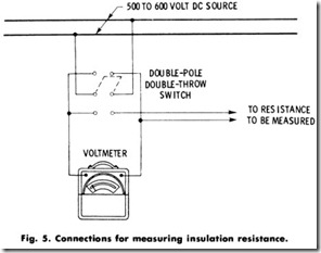
Measurements of insulation resistance are most readily obtained with a megger or an ohmmeter. For general maintenance work the megger should be of the 500-volt rating, although for special tests a 1000-volt or even 2500-volt megger may be required. When a 500-volt or 600-volt de circuit is available, satisfactory results may be secured with a de voltmeter having high internal resistance. The method of measurement is to first read the voltage of the line, and then to connect the resistance to be measured in series with the voltmeter and take a second reading. The measured resistance is then calculated by using the following formula:
where,
V is the voltage of the line,
v is the voltage reading with the insulation in series with the voltmeter,
r is the resistance of the voltmeter in ohms (generally marked on the label inside the instrument cover),
R is the resistance of the insulation in megohms (1,000,000 ohms).
The method of connecting the apparatus is shown in Fig. 5.
If a grounded circuit is used in making this measurement, care must be taken to connect the grounded side of the line to the frame of the apparatus to be measured, and the voltmeter between the windings and the other side of the circuit.
Voltmeters having a resistance of 1 megohm are now made for taking insulation resistance measurements. If one of these instruments is used, the calculation is somewhat simplified since r = 1 and the foregoing formula becomes:
As an example, in testing a motor insulated for 13,800-volt service with a line voltage, V, of 600, using a voltmeter having an internal resistance, r, of 1,000,000 ohms (1 megohm), and assuming the voltage, (v), indication with the meter in series with the insulation to be 40:
Then:
or, since this is a megohm meter:
A safe general rule is that the insulation resistance should be approximately 1 megohm for each 1000 operating volts, with a min imum value of 1 megohm. No new apparatus should have an insulation resistance of less than 1 megohm.
Insulation resistance of apparatus in service should be checked periodically at approximately the same temperature and under similar conditions of humidity to determine possible deterioration of the in sulation. When such measurements, made at regular intervals as a part of the general-maintenance routine, show wide variations in insulation resistance, the cause should be determined and abnormal conditions should be corrected before an insulation failure occurs.
Dielectric Strength
The purpose of the dielectric tests is to determine whether the insulation will withstand the voltage stresses occurring during normal or assumed abnormal conditions of operation. The assurance provided by a dielectric test may warrant the risk involved in applying it as preventive maintenance prior to a critical period of operation. The damage result ing from an insulation failure at the time of a properly applied dielectric or high-voltage test is likely to be slight compared to the loss caused by a breakdown while the apparatus is carrying an important load.
For example, in the chemical industry, such a breakdown might ruin the product of many days’ operations, with more days being required to bring up the process to the stage at the time of the failure, even if other electrical apparatus were immediately available. Furthermore, the ad ditional cost of repairs resulting from the failure under load must be given consideration.
The insulation of electrical apparatus that has been repaired or reconstructed should be given a dielectric test. Samples of insulating oil taken from transformers, induction regulators, and circuit breakers should be tested for breakdown value at regular intervals. Dielectric tests are a part of the regular test procedures of the manufacturers of electrical apparatus. The Standards of the Institute of Electrical & Electronic Engineers (IEEE) is the accepted authority for these tests.
Dielectric tests are generally made with alternating current of com mercial frequency (25-60 hertz) for a period of 60 seconds. De high voltage tests are being used to a limited extent in testing insulation. Their principal use is for determining the dielectric characteristics of cables and for laboratory work. Research is being carried on to develop these tests for the commercial testing of electrical-apparatus insulation. A decided advantage of high-voltage de for maintenance insulation testing is the greatly reduced weight and size of the testing equipment required for checking large, high-voltage apparatus and machines.
Dielectric test voltage values have been established for apparatus that has been operated in commercial service, nor is there authorization for dielectric tests for windings that have been repaired. It is rather general practice, however, to apply from 65% to 75% of the authorized test voltage for new apparatus. Because many of the conditions affecting such tests are extremely variable, the decision concerning procedure is generally made by the maintenance department engineer.


