Motor Principles
In order to obtain a clear concept of the principles on which the electric motor operates, it is necessary first to understand the funda mental laws of magnetism and magnetic induction. It is not necessary to have a great number of expensive laboratory instruments to obtain this know ledge -instead, children’s toy magnets, automobile accessories, etc., will suffice. It is from these principles that the necessary knowl edge about the behavior of permanent magnets and the magnetic needle can be obtained.
In our early schooldays, we learned that the earth is a huge permanent magnet with its north magnetic pole somewhere in the Hudson Bay region and that the compass needle points toward the magnetic pole. The compass is thus an instrument that can give an indication of magnetism.
The two spots on the magnet which point one to the north and the other to the south, are called the poles -one is called the north-seek ing pole (N) and the other the south-seeking pole (S).
MAGNETIC AnRACTION AND REPULSION
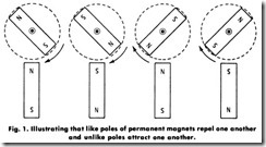
If the south-seeking, or S, pole of a magnet is brought near the S pole of a suspended magnet, as in Fig. 1, the poles repel each other. If the two N poles are brought together, they also repel each other. But if a N pole is brought near the S pole of the moving magnet, or aS pole toward theN pole, the two unlike poles attract each other. In other words, like poles repel each other, and unlike poles attract each other. It can also be shown by experiment that these attractive or repulsive forces be tween magnetic poles vary inversely as the square of the distance between the poles.
EHects of an Electric Current
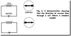
As a further experiment, connect a coil to a battery as shown in Fig.2. Here it will be noticed that the compass points to one end of the coil, but if the battery connections are reversed, the compass points away from that end. Thus, the direction of the current through the coil affects the compass in a manner similar to the permanent magnet in the previous experiment.
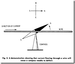
In the early part of the 18th Century, Oersted made the discovery showing the relationship existing between magnetism and electricity. He observed that when a wire connecting the poles of a battery was held over a compass needle, the north pole of the needle was deflected toward the west when the current flowed from south to north, as shown in Fig. 3, while a wire placed under the compass needle caused the north pole of the needle to be deflected toward the east.
Magnetic Field of an Electric Current
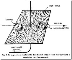
Inasmuch as the compass needle indicates the direction of magnetic lines of force, it is evident from Oersted’s experiment that an electric current sets up a magnetic field at right angles to the conductor. This can be shown by the experiment illustrated in Fig. 4. If a strong current is sent through a vertical wire which passes through a horizontal piece of cardboard on which iron filings are placed, a gentle tap of the board causes the iron filings to arrange themselves in concentric rings about the wire. By placing a compass at various positions on the board, the direction of these lines of force is as shown in Fig. 4.
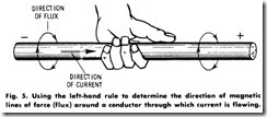
A convenient rule for remembering the direction of the magnetic flux around a straight wire carrying current is the so-called left-hand rule. With reference to Fig. 5, it can be seen that if the wire is held by the left hand, with the thumb pointing in the direction of the current, the fingers will point in the direction of the magnetic field.
Con verseIy, if the direction of the magnetic field around a conductor is known, the direction of the current in the conductor can be found by applying this rule.
ELECTROMAGNETS
A soft-iron core surrounded Ly a coil of wire is called an elec tromagnet. The electromagnet owes its great utility, not so much to its great strength, as to its ability to change its magnetic strength with the strength of the applied current. Such an electromagnet is a magnet only when the current flows through its coil. When the current is interrupted, the iron core returns almost to its natural state. This loss of magnetism is, however, not absolutely complete since a very small amount, called residual magnetism, remains.
An electromagnet is a part of nearly all electrical devices, including electric bells, telephones, motors, and generators.
The polarity of an electromagnet may be determined by means of the right-hand rule used for a straight wire as follows: Grasp the coil with the left hand so that the fingers point in the direction of the current in the coil, and the thumb will point to the north pole of the coil. See Fig. 6.
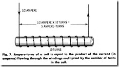
The strength of an electromagnet depends on the strength of the current (in amperes) times the number of loops of wire (turns)-that is, the ampere-turns of the coil (Fig. 7). In practical electromagnets, it is customary to make use of both poles by bending the iron core and the coil in the form of a horseshoe. It is from this form that the name horseshoe magnet is derived.
INDUCED CURRENTS
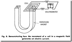
If the ends of a coil of wire having many turns are connected to a sensitive galvanometer, as shown in Fig. 8, and the coil is moved up and down over one pole of a horseshoe magnet, a deflection of the galvanometer pointer will be observed. It will also be noted that in lowering the coil, the deflection of the galvanometer pointer will be in a direction opposite that of the needle when the coil is raised. When the coil is lowered and held down, the galvanometer pointer returns to zero. This experiment shows that it is possible to produce a momentary electric current without an apparent electrical source.
The electric current produced by moving the coil in a magnetic field is called an induced current. It is evident from the experiment that the current is induced only when the wire is moving, and that the direction of the current is reversed when the motion changes direction. Since an electric current is always made to flow by an electromotive force (emf), the motion of a coil in a magnetic field must generate and produce an induced electromotive force.
The direction of an induced current may be stated as follows: An induced current has such a direction that its magnetic action tends to resist the motion by which it isproduced. This is known as Lenz ‘slaw.
The most useful application of induced currents is in the construction of electrical machinery of all sorts, the most common of which are the generator and motor.
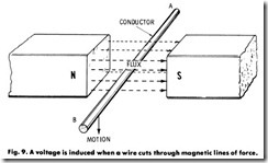
A simple way to obtain a fundamental understanding of the generator is to think of the induced electromotive force (emf) produced in a single wire when it is moved across a magnetic field. Suppose wire AB in Fig.9 is pushed down through the magnetic field. An induced emf is set up in AB, making point B at a higher potential than point A. This can be shown by connecting a voltmeter from A to B.
As long as the wire remains stationary, no current flows. In fact, even if the wire moves parallel to the lines of force, no current flows. Briefly, a wire must move so as to cut lines of magnetic force in order to have an emf induced in it.
DIRECT-CURRENT GENERATOR
A machine converting mechanical energy into electrical energy is called a generator. Its essential parts are:
1. A magnetic field, usually produced by permanent magnets.
2. A moving coil or coils, called the armature.
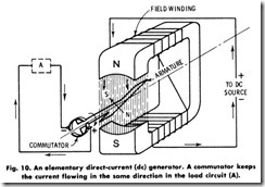
In a direct-current (de) machine (Fig. 10), a mechanical device called a commutator is used to reverse the connections to the revolving conductors in the generator at the instant the current in them is reversing. Each end of the loop of wire is connected to one segment of the commutator, with each segmert insulated from the others.
The sliding contacts, or brushes, are so placed that the current always flows from the loop into one brush and from the other brush into the loop, regardless of which relative direction the current in the loop itself flows. In this way the brushes carry current flowing in one direction only. The brushes or terminals are designated by the terms positive (+, plus) and negative (-,minus) to indicate the direction in which the current is assumed to flow.
DIRECT-CURRENT MOTOR
A machine converting electrical energy into mechanical energy is called a motor. The functions of a de generator and a de motor are interchangeable in that a generator may be operated as a motor, and vice versa. Structurally, the two machines are identical. The motor, like the generator, consists of an electromagnet, an armature, and a commutator with its brushes.
Fig. 10 will serve to illustrate the operation of a direct-current motor as well as a generator. The magnetic field, as indicated, will be the same for a motor because of current flowing in the field windings. Now, let the outside current at A have a voltage applied which causes a current to flow in the armature loop, as indicated by the arrows.
It must be remembered that any current flowing in a loop or coil of wire produces a magnetic field. 1 his is exactly what happens in the armature of this motor. In addition, a second magnetic field is produced, with poles N and S perpendicular to the armature loop. The north pole of the main magnetic field attracts the south pole of the armature, and since the loop is free, it will revolve. At the instant the north and south poles become exactly opposite, however, the commutator reverses the current in the armature, making the poles of the field and the armature opposite, and the loop is then repelled and forced to revolve further. Again the armature current is reversed when unlike poles approach, and the armature is free to revolve. This continues as long as there is current in the armature and field windings.
It should be observed that, in an actual motor, there is more than one loop (called an armature coil), each with its terminals connected to adjacent commutator segments. Hence, the attracting and repelling action is correspondingly more powerful and also more uniform than that of the weak and unstable action obtained with the single-loop armature described here.
The various types of direct -current motors as well as their operating characteristics and control methods are fully treated in a later chapter.
ALTERNATING-CURRENT MOTOR
When a coil of wire is rotated in a magnetic field, the current changes its direction every half turn. Thus, there are two alternations of current for each revolution of a bipolar machine. As previously noted, this alternating current is rectified by the use of a commutator in a direct current generator. In an alternating-current generator, also termed an alternator, the current induced in the armature is led out through slip rings or collector rings, as shown in Fig. 11.
A magnetic field is established between the north pole and the south pole by means of an exciting current flowing in winding W. A loop of wire, L, in this field is arranged so that it can be rotated on axis X, and the ends of this loop are brought out to slip rings SS, on which brushes BB can slide.
This circuit, of which this rotating loop is a part, is completed through the slip rings at A. When the loop is rotating, conductorsF and G have a voltage produced in them which will cause a current to flow out to A , where the circuit is completed.
The simplified machine represented in Fig. 11 is a two-pole, single phase, revolving-armature, alternating-current generator. The magnetic field-the coils of wire and iron core-are called simply the field of the generator. The rotating loop in which the voltage is induced is called the armature.
The rotating armature type of generator is generally used only on small machines, whereas large machines almost without exception are built with rotating fields.
If the voltage completes 60 cycles in one second, the generator is termed a 60-hertz machine. The current that this voltage will cause to flow will be a 60-hertz current. The term hertz indicates cycles per second.
