Determining Motor Current
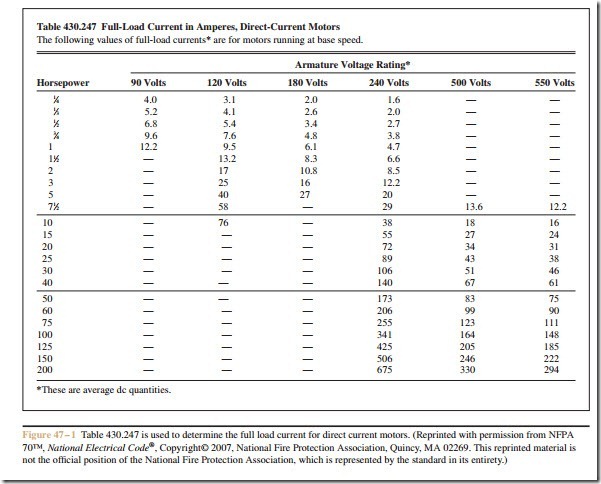
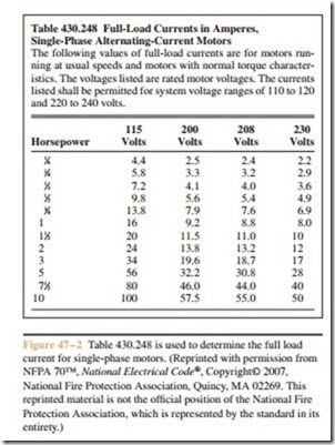
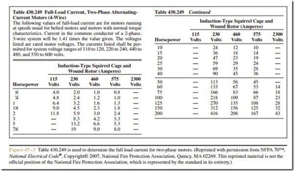
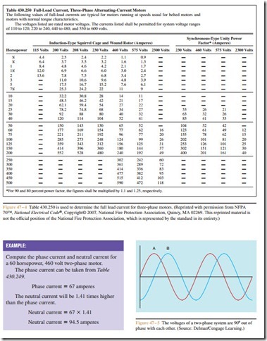
There are different types of motors, such as direct cur- rent, single-phase AC, two-phase AC, and three-phase AC. Different tables from the National Electrical Code (NEC)® are used to determine the running cur- rent for these different types of motors. Table 430.247 (Figure 47 – 1) is used to determine the full load running current for a direct current motor. Table 430.248 (Figure 47 – 2) is used to determine the full load running current for single-phase motors; Table 430.249 (Figure 47 – 3) is used to determine the running cur- rent for two-phase motors; and Table 430.250 (Figure 47 – 4) is used to determine the full load running current for three-phase motors. Note that the tables list the amount of current that the motor is expected to draw under a full load condition. The motor will exhibit less current draw if it is not under full load. These tables list the ampere rating of the motors according to horsepower and connected voltage. It should also be noted that NEC Section 430.6(A)(1) states these tables are to be used to in determining conductor size, short circuit protection size, and ground fault protection size instead of the nameplate rating of the motor. The motor overload size, however, is to be determined by the nameplate rating of the motor.
Direct Current Motors
Table 430.247 lists the full load running currents for direct current motors. The horsepower rating of the motor is given in the far left-hand column. Rated volt- ages are listed across the top of the table. The table
shows that a 1 horsepower motor will have a full-load current of 12.2 amperes when connected to 90 volts DC. If a 1 horsepower motor is designed to be connected to 240 volts, it will have a current draw of 4.7 amperes.
Single-Phase AC Motors
The current ratings for single-phase AC motors are given in Table 430.248. Particular attention should be paid to the statement preceding the table. The statement asserts that the values listed in this table are for motors that operate under normal speeds and torques. Motors especially designed for low speed and high torque, or multispeed motors, should have their running current determined from the nameplate rating of the motor.
The voltages listed in the table are 115, 200, 208, and 230. The last sentence of the preceding statement says that the currents listed shall be permitted for volt- ages of 110 to 120 volts and 220 to 240 volts. This means that if the motor is connected to a 120 volt line, it is permissible to use the currents listed in the 115 volt column. If the motor is connected to a 220 volt line, the 230 volt column can be used.
EXAMPLE:
A 3 horsepower single-phase AC motor is connected to a 208 volt line. What will be the full load running current of this motor?
Locate 3 horsepower in the far left-hand column. Follow across to the 208 volt column. The full load current will be 18.7 amperes.
Two-Phase Motors
Although two-phase motors are seldom used, Table 430.249 lists the full load running currents for these motors. Like single-phase motors, two-phase motors that are especially designed for low speed, high torque applications and multispeed motors, use the nameplate rating instead of the values shown in the table. When using a two-phase, three-wire system, the size of the neutral conductor must be increased by the square root of 2, or
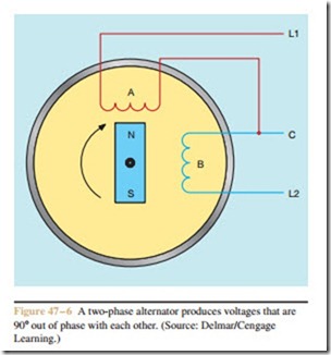
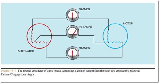
1.41. The reason for this is that the voltages of a two- phase system are 90 degrees out-of-phase with each other, as shown in Figure 47 – 5. The principle of two- phase power generation is shown in Figure 47 – 6. In a two-phase alternator, the phase windings are arranged 90 degrees apart. The magnet is the rotor of the alternator. When the rotor turns, it induces voltage into the phase windings, which are 90 degrees apart. When one end of each phase winding is joined to form a common terminal, or neutral, the current in the neutral conductor will be greater than the current in either of the two phase conductors. An example of this is shown in Figure 47 – 7. In this example, a two-phase alternator is connected to a two-phase motor. The current draw on each of the phase windings is 10 amperes. The current flow in the neutral, however, is 1.41 times greater than the current flow in the phase windings, or 14.1 amperes.
Three-Phase Motors
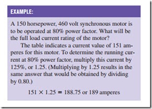
Table 430.250 is used to determine the full load current of three-phase motors. The notes at the top of the table are very similar to the notes of Tables 430.248 and 430.249. The full load current of low speed, high torque and multispeed motors is to be determined from the nameplate rating instead of from the values listed in the table. Table 430.250 has an extra note that deals with synchronous motors. Notice that the right-hand side of Table 430.250 is devoted to the full load currents of synchronous type motors. The currents listed are for synchronous type motors that are to be operated at unity, or 100%, power factor. Since synchronous motors are often made to have a leading power factor by over excitation of the rotor current, the full load current rating must be increased when this is done. If the motor is to be operated at 90% power factor, the rated full load current in the table must be increased by 10%. If the motor is to be operated at 80% power factor, the full load current is to be increased by 25%.
A 200 horsepower, 2300 volt synchronous motor is to be operated at 90% power factor. What will be the full load current rating of this motor?
Locate 200 horsepower in the far left-hand col- umn. Follow across to the 2300 volt column listed under synchronous type motors. Increase this value by 10%:
40 X 1.10 = 44 amperes
Determining Conductor Size for a Single Motor
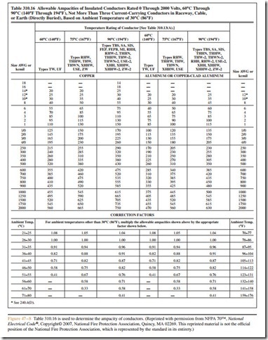
NEC Section 430.6(A)(1) states that the conductor for a motor connection shall be based on the values from Tables 430.247, 430.248, 430.249, and 430.250 instead of the motor nameplate current. Section 430.22(A) states that conductors supplying a single motor shall have an ampacity of not less than 125% of the motor full load current. NEC Section 310 is used to select the conductor size after the ampacity has been determined. The exact table employed will be determined by the wiring conditions. Probably the most frequently used table is 310.16 (Figure 47 – 8).
Termination Temperature
Another factor that must be taken into consideration when determining the conductor size is the temperature rating of the devices and terminals as specified in NEC Section 110.14(C). This section states that the conductor is to be selected and coordinated as to not exceed the lowest temperature rating of any connected termination, any connected conductor, or any con- nected device. This means that, regardless of the tem- perature rating of the conductor, the ampacity must be selected from a column that does not exceed the temperature rating of the termination. The conductors listed in the first column of Table 310.16 have a temperature rating of 60°C, the conductors in the second column have a rating of 75°C, and the conductors in the third column have a rating of 90°C. The temperature ratings of devices such as circuit breakers, fuses, and terminals are often found in the UL (Underwriters Lab- oratories) product directories. Occasionally, the temperature rating may be found on the piece of equipment, but this is the exception and not the rule. As a general rule, the temperature rating of most devices will not exceed 75°C.
When the termination temperature rating is not listed or known, NEC Section 110.14(C)(1)(a) states that for circuits rated at 100 amperes or less, or for #14 AWG through #1 AWG conductors, the ampacity of the wire, regardless of the temperature rating, will be se- lected from the 60°C column. This does not mean that only those types of insulations listed in the 60°C col- umn can be used, but that the ampacities listed in the 60°C column must be used to select the conductor size. For example, assume that a copper conductor with type XHHW insulation is to be connected to a 50 ampere circuit breaker that does not have a listed temperature rating. According to NEC Table 310.16, a #8 AWG copper conductor with XHHW insulation is rated to carry 55 amperes of current. Type XHHW insulation is located in the 90°C column, but the temperature rating of the circuit breaker is not known. Therefore, the wire size must be selected from the ampacity ratings in the 60°C column. A #6 AWG copper conductor with type XHHW insulation would be used.
NEC Section 110.14(C)(1)(a)(4) has a special pro- vision for motors with marked NEMA design codes
EXAMPLE:
A 30 horsepower three-phase squirrel cage induc- tion motor is connected to a 480 volt line. The con- ductors are run in conduit to the motor. The motor does not have a NEMA design code listed on the nameplate. The termination temperature rating of the devices is not known. Copper conductors with THWN insulation are to be used for this motor connection. What size conductors should be used?
The first step is to determine the full load cur- rent of the motor. This is determined from Table 430.250. The table indicates a current of 40 am- peres for this motor. The current must be increased by 25% according to Section 430.22(A).
40 X 1.25 = 50 amperes
Table 310.16 is used to determine the conductor size. Locate the column that contains THWN insulation in the copper section of the table. THWN is located in the 75°C column. Since this circuit is less than 100 amperes and the termination temperature is not known, and the motor does not contain a NEMA design code letter, the conductor size must be selected from the ampacities listed in the 60°C column. A #6 AWG copper conductor with type THWN insulation will be used.
B, C, or D. This section states that conductors rated at 75°C or higher may be selected from the 75°C column even if the ampacity is 100 amperes or less. This code will not apply to motors that do not have a NEMA de- sign code marked on their nameplate. Most motors manufactured before 1996 will not have a NEMA de- sign code. The NEMA design code letter should not be confused with the code letter that indicates the type squirrel cage rotor used in the motor.
For circuits rated over 100 amperes, or for conductor sizes larger than #1 AWG, Section 110.14(C)(1)(b) states that the ampacity ratings listed in the 75°C column may be used to select wire sizes unless conductors with a 60°C temperature rating have been selected for use. For example, types TW and UF insulation are listed in the 60°C column. If one of these two insulation types has been specified, the wire size must be chosen from the 60°C column regardless of the ampere rating of the circuit.
