MAGNETIC CONTROL
A high percentage of applications require the controller to be capable of operation from remote locations, or to provide automatic operation in response to signals from pilot devices such as thermostats, pressure or float switches, limit switches, etc. Low-voltage release or protection might also be desired. Manual starters cannot provide this type of control, and therefore magnetic starters are used.
The operating principle which distinguishes a magnetic from a manual starter is the use of an electromagnet (Fig. 23). The electro magnet consists of a coil of wire placed on an iron core. When current flows through the coil, the iron bar, called the armature, is attracted by the magnetic field created by the current in the coil. To this extent both will attract the iron bar (the arms of the core). The electromagnet can be compared to the permanent magnet shown in Fig. 23.
The field of the permanent magnet, however, will hold the armature against the pole faces of the magnet indefinitely. The armature could not be dropped out except by physically pulling it away. In the electro magnet, interrupting the current flow through the coil of wire causes the armature to drop out due to the presence of an air gap in the magnetic circuit.
With manual control, the starter must be mounted so that it is easily accessible to the operator. With magnetic control, the push-button stations or other pilot devices can be mounted anywhere on the machine, and connected by control wiring into the coil circuit of the remote Iy mounted starter.
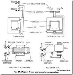
Magnet Frame and Armature Assemblies-In the construction of a magnetic controller, the armature is mechanically connected to a set of contacts, so that when the armature moves to its closed position, the contacts also close. The drawings in Fig. 24 show several magnet and armature assemblies in elementary form. When the coil has been energized, and the armature has moved to the closed position, the controller is said to be “picked up,” and the armature “seated” or sealed-in.
Magnetic Circuit-The magnetic circuit of a controller consists of the magnet assembly, the coil and the armature. It is so named from a comparison with an electrical circuit. The coil and the current flowing in it cause magnetic flux to be set up through the iron in a similar manner to a voltage causing current to flow through a system of conductors. The changing magnetic flux produced by alternating currents results in a temperature rise in the magnetic circuit. The heating effect is reduced by laminating the magnet assembly and armature.
Magnet Assembly-The magnet assembly is the stationary part of the magnetic circuit. The coil is supported by and surrounds part of the magnet assembly in order to induce magnetic flux into the magnetic circuit.
Armature-The armature is the moving part of the magnetic circuit.
When it has been attracted into its sealed-in position, it completes the magnetic circuit.
Air Gap-When a controller’s armature has sealed-in, it is held closely against the magnet assembly. However, a small gap is always deliberately left in the iron circuit. When the coil is deenergized, some magnetic flux (residual magnetism) always remains-and if it were not for the gap in the iron circuit, the residual magnetism might be sufficient to hold the armature in the sealed-in position (Fig. 25).
Shading Coil-A shading coil is a single turn of conducting material (generally copper or aluminum) mounted in the face of the magnet assembly or armature. Fig. 26. The alternating main magnetic flux induces currents in the shading coil and these currents set up auxiliary magnetic flux which is out of phase from the main flux. The auxiliary flux produces a magnetic pull that is out of phase from the pull due to the main flux, and this keeps the armature sealed-in when the main flux falls to zero (which occurs 120 times per second with 60-hertz ac). Without the shading coil, the armature would tend to open each time the main flux goes through zero. Excessive noise, wear on the magnet faces, and heat would occur (Fig. 27).
Effects of Voltage Variation (Voltage Too Low)-Low control voltage produces low coil currents and reduced magnetic pull. On devices with vertical action assemblies, if the voltage is greater than pick-up voltage but less than seal-in voltage, the controller may pick up but will not seal. With this condition, the coil current will not fall to the sealed value. As the coil is not designed to carry continuously a current greater than its sealed current, it will quickly get very hot and burn out. The armature will also chatter. In addition to the noise, wear on the magnet faces results (Fig. 28).
Ac Hum-All ac devices which incorporate a magnetic effect pro duce a characteristic hum. This hum or noise is due mainly to the changing magnetic pull (as the flux changes) inducing mechanical vibrations. Contactors, starters and relays could become excessively noisy as a result of some of the following operating conditions:
1 . Broken shading coil,
2. Operating voltage too low,
3. Wrong coil,
4. Misalignment between the armature and magnet assembly-the armature is then unable to seat properly,
5. Dirt, rust, filings etc. on the magnet faces-the armature is unable to seal in completely,
6. Jamming or binding of moving parts (contacts, springs, guides, yoke bars) so that full travel of the armature is prevented,
7. Incorrect mounting of the controller, as on a thin piece of plywood fastened to a wall, for example, so that a “sounding board” effect is produced.
HOLDING CIRCUIT INTERLOCK
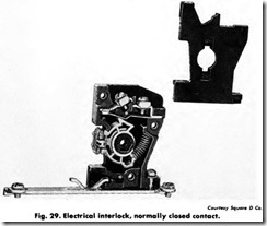
The holding circuit interlock is a normally open (NO) auxiliary contact provided on standard magnetic starters and contactors. It closes when the coil is energized to form a holding circuit for the starter after the “start” button has been released. As a matter of economics, vertical action contactors and starters in the smaller NEMA sizes (size 0 and size
1) have a holding interlock which is physically the same size as the power contacts (Fig. 29).
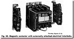
Electrical Interlocks-In addition to the main or power contacts which carry the motor current, and the holding circuit interlock, a starter can be provided with externally attached auxiliary contacts, commonly known as electrical interlocks. Interlocks are rated to carry only control circuit currents, not motor currents. NO and NC versions are available.
Among a wide variety of applications, interlocks can be used to control other magnetic devices where sequence operation is desired; to electrically prevent another controller from being energized at the same time; and to make and break circuits to indicating or alarm devices such as pilot lights, bells or other signals.
Electrical interlocks are packaged in kit form, and can be easily added in the field. Fig. 30.
Control Device (pilot device)-A device which is operated by some nonelectrical means (such as the movement of a lever), and which has contacts in the control circuit of a starter, is called a “control device.” Operation of the control device will control the starter and hence the motor. Typical control devices are control stations, limit switches, foot switches, pressure switches, and float switches. The control device may be of the maintained contact or momentary contact type. Some control devices have a horsepower rating, and are used to directly control small motors through the operation of their contacts. When used in this way, separate overload protection (such as a manual starter) normally should be provided, as the control device does not usually incorporate over load protection.
Maintained Contact-A maintained-contact control device is one which, when operated, will cause a set of contacts to open (or close) and stay open (or closed) until a deliberate reverse operation occurs. A conventional thermostat is a typical maintained-contact device.
Momentary Contact-A standard push button is a typical momentary contact control device. Pushing the button will cause NO contacts to close and NC contacts to open. When the button is released, the contacts revert to their original states. Momentary-contact devices are used with 3-wire control or jogging service.
REVERSING STARTER
Reversing the direction of motor shaft rotation is often required. Three-phase squirrel cage motors can be reversed by reconnecting any two of the three line connections to the motor. By interwiring two contactors, an electromagnetic method of making the reconnection can be obtained.
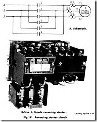
As seen in the power circuit (Fig. 31A) the contacts F of the forward contactor, when closed, connect lines 1, 2 and 3 to motor terminals T1, T2 and T3 respectively. As long as the forward contacts are closed, mechanical and electrical interlocks prevent the reverse contactor from being energized.
When the forward contactor is deenergized, the second contactor can be picked up, closing its contacts R which reconnect the lines to the motor. Note that by running through the reverse contacts, Line 1 is connected to motor terminal T3 and line 3 is connected to motor terminal T1 . The motor will now run in the opposite direction.
Whether operating through either the forward or reverse contactor, the power connections are run through an overload relay assembly, which provides motor overload protection. A magnetic reversing starter, therefore, consists of a starter and contactor, suitably inter wired, with electrical and mechanical interlocking to prevent the coil of both units from being energized at the same time. Fig. 31B shows size 1 , 3-pole reversing starter as it looks in operation.
TIMERS AND TIMING RELAYS
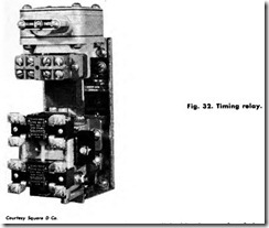
A pneumatic timer or timing relay is similar to a control relay, except that certain portions of its contacts are designed to operate at a preset time interval after the coil is energized or deenergized. A delay on energization is also referred to as on delay.” A time delay on deenergization is called ”off delay.”
A timed function is useful in applications such as the lubricating system of a large machine, in which a small oil pump must deliver lubricant to the bearings of the main motor for a set period of time before the main motor starts. Fig. 32.
In pneumatic timers , the timing is accomplished by the transfer of air through a restricted orifice. The amount of restriction is controlled by an adjustable needle valve, permitting changes to be made in the timing period.
DRUM SWITCH
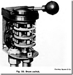
A drum switch is a manually operated 3-position, 3-pole switch which carries a horsepower rating and is used for manual reversing of single or 3-phase motors. Drum switches are available in several sizes, and can be spring-return-to-off (momentary contact) or maintained contact. Separate overload protection, by manual or magnetic starters, must usually be provided, as drum switches do not include this feature (Fig. 33).
CONTROL STATION (PUSH BUTTON STATION)
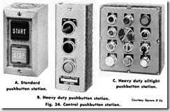
A control station may contain push buttons, selector switches and pilot lights. Push buttons may be momentary or maintained contact. Selector switches are usually maintained contact, or can be spring return to give momentary contact operation. Standard duty stations will handle the coil currents of contactors up to Size 4. Heavy duty stations have higher contact ratings and provide greater flexibility through a wider variety of operators, and interchangeability of units, Fig. 34, A, B, and C.
LIMIT SWITCH
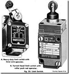
A limit switch is a control device which converts mechanical motion into an electrical control signal. Its main function is to limit movement, usually by opening a control circuit when the limit of travel is reached. Limit switches may be momentary-contact (spring-return) or main tained-contact types. Among other applications, limit switches can be used to start, stop, reverse, slow down, speed up or recycle machine operations (Fig. 35 A, and B).
SNAP SWITCH
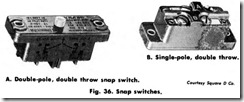
Snap switches for motor control purposes are enclosed precision switches which require low operating forces and have a high repeat accuracy. They are used as interlocks, and as the switch mechanism for control devices such as precision limit switches, and pressure switches. They are available also with integral operators for use as compact limit switches, door-operated interlocks, etc. Single-pole double-throw and 2-pole double-throw are available (Fig. 36 A, and B).
PRESSURE SWITCH
The control of pumps, air compressors, welding machines, lube systems, and machine tools requires control devices which respond to the pressure of a medium such as water, air, or oil. The control device which does this is a pressure switch. It has a set of contacts which are operated by the movement of a piston, bellows or diaphragm against a set of springs. The spring pressure determines the pressures at which the switch closes and opens its contacts.
FLOAT SWITCH
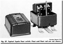
When a pump motor must be started and stopped according to changes in water (or other liquid) level in a tank or sump, a float switch is used. This is a control device whose contacts are controlled by movement of a rod or chain and counterweight, fitted with a float. For closed tank operation, the movement of a float arm is transmitted through a bellows seal to the contact mechanism (Fig. 37).
The information and pictures herein have been furnished by Square D Company. Some of the material has been copyrighted by SquareD and this publication does not claim copyright for such information. Square D assumes no obligations or liabilities arising from reproduction.
SUMMARY
The squirrel-cage induction motor is the most widely used. It is the workhorse of industry. An electric motor should be matched to the electrical service.
The fundamental job of a controller is to start and stop the motor. It should also protect the motor, machine and operator. Controllers are enclosed to provide protection for operating personnel by preventing accidental contact with live parts.
Motor controls are designed to meet the provisions of the National Electric Code. Standards established by the National Electrical Man ufactures Association assist users in the proper slection of control equipment.
Current required to produce full load torque at rated speed is called FLC. Locked rotor current is nothing more than the inrush current which occurs when the motor is first energized by line voltage. Locked rotor current can be from 4 to 10 times the motor full load current.
Motor speed of a squirrel-cage motor depends of the number of poles on the motor winding. The torque is the turning or twisting force of the motor and is usually measured in pound-feet or in metric kilogram meters or gram-centimeters.
Motor controllers are used for jogging, plugging and sequence control steps. Derating of the controls are sometimes called for when the frequency of operation is jogging, plugging or sequencing is abnormal.
Overcurrent protection is provided motors to protect the motor branch circuit conductors, control appratus and motor from short circuits or grounds.
Overloads shorten motor life by deteriorating the insulation. The ideal overload protection from a motor is an element with current sensing properties very similar to the heating curve of the motor. Fuses are designed to provide overload protection. Overload relays are ac tuated by a sensing unit. They may be taken out of the circuit by breaking the coil circuit. This opens the starter contacts disconnecting the motor from the line.
The holding circuit interlock is a normally open auxiliary contact provided on standard magnetic starters and contactors. It closes when the coil is energized to form a holding circuit for the starter after the start,, button has been released.
Reversing the direction of motor rotation is often required. Three phase squirrel-cage motors can be reversed by reconnecting any two of the three line connections to the motor.
A drum switch is a manually operated 3-position, 3-pole switch which carries a horsepower rating and is used for manual reversing of a single or 3-phase motor. Limit switches, snap switches and float switches are examples of other types of control devices.
REVIEW QUESTIONS
1. What is a motor controller’s main purpose?
2. What standards must the controller be designed to meet?
3. What is the Code referred to as being complied with in the use of controllers?
4. What is meant by derating a controller?
![Fig.-23.-A-electromagnet-and-a-perma[1] Fig.-23.-A-electromagnet-and-a-perma[1]](http://machineryequipmentonline.com/electric-equipment/wp-content/uploads/2020/06/Fig.-23.-A-electromagnet-and-a-perma1_thumb.jpg)
![Fig.-25.-Air-gap-shown-in-center-sec[2] Fig.-25.-Air-gap-shown-in-center-sec[2]](http://machineryequipmentonline.com/electric-equipment/wp-content/uploads/2020/06/Fig.-25.-Air-gap-shown-in-center-sec2_thumb.jpg)
![Fig.-26.-Magnet-assembly-and-armatur[1] Fig.-26.-Magnet-assembly-and-armatur[1]](http://machineryequipmentonline.com/electric-equipment/wp-content/uploads/2020/06/Fig.-26.-Magnet-assembly-and-armatur1_thumb.jpg)
![Fig.-27.-Shading-coil-current-vs-mag[2] Fig.-27.-Shading-coil-current-vs-mag[2]](http://machineryequipmentonline.com/electric-equipment/wp-content/uploads/2020/06/Fig.-27.-Shading-coil-current-vs-mag2_thumb.jpg)
![Fig.-28.-Magnetic-starter-power-circ[1] Fig.-28.-Magnetic-starter-power-circ[1]](http://machineryequipmentonline.com/electric-equipment/wp-content/uploads/2020/06/Fig.-28.-Magnetic-starter-power-circ1_thumb.jpg)
