Methods of Motor Control
Since over 90% of all motors are used on ac, de motors and their controls will not be discussed in this chapter.
Wound rotor motors and ac commutator motors have a limited application and are also not included. The squirrel-cage induction motor is the most widely used. Therefore, its control is the subject of this chapter. The use of higher voltages (2400, 4800, and higher) introduces requirements which are additional to those for 600-volt equipment, and although the basic principles are unchanged, these additional require ments are not covered here.
SELECTION OF MOTOR CONTROL
The motor, machine, and motor controller are interrelated. They need to be considered as a package when choosing a specific device for a particular application. In general, five basic factors influence the selec tion of a controller:
Electrical Service-Establish whether the service is de or ac. If ac,
determine the number of phases and the frequency-in addition to the voltage.
Motor-The motor should be matched to the electrical service. The motor should be correctly sized for the machine load (horsepower rating). Other considerations include the motor speed and torque. To select the proper protection for the motor, its full load current rating, service factor, and time rating must be known.
Operating Characteristics of the Controller-The fundamental job of a motor controller is to start and stop the motor. It should also protect the motor, machine and operator.
The controller might also be called upon to provide supplementary functions, which could include reversing, jogging or inching, plugging operating at several speeds or at reduced levels of current and motor torque.
Environment-Controller enclosures serve to provide protection for operating personnel by preventing accidental contact with live parts. In certain applications, the controller itself must be protected from a variety of environmental conditions which might include:
Water, rain, snow, or sleet,
Dirt or noncombustible dust,
Cutting oils, coolants, or lubricants.
Both personnel and property require protection in environments made hazardous by the presence of explosive gases or combustible dusts.
National Codes and Standards-Motor control equipment is de signed to meet the provisions of the National Electrical Code (NEC). Code sections applying to industrial control devices are Article 430 on motors and motor controllers and Article 500 on hazardous locations.
The 1970 Occupational Safety and Health Act (OSHA) as amended in 1972, requires that each employer furnish employment free from recognized hazards likely to cause serious harm. Provisions of the act are strictly enforced by inspection.
Standards established by the National Electrical Manufacturers As sociation (NEMA) assist users in the proper selection of control equipment. NEMA standards provide practical information concerning construction, test, performance and manufacture of motor control devices such as starters, relays and contactors.
One of the organizations which actually tests for conformity to national codes and standards is Underwriter’s Laboratories (UL).
Equipment tested and approved by UL is listed in an annual publication, which is kept current by means of bimonthly supplements which reflect the latest additions and deletions.
MOTOR CONTROLLER
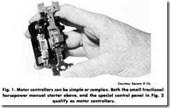
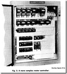
A motor controller will include some or all of the following func tions: starting, stopping, overload protection, overcurrent protection, reversing, changing speed, jogging, plugging, sequence control, and pilot light indication. The controller can also provide the control for auxiliary equipment such as brakes, clutches, solenoids, heaters, and signals. A motor controller may be used to control a single motor or a group of motors. Fig. 1.
Starter
The terms Hstarter” and “controller” mean practically the same thing. Strictly speaking, a ‘starter” is the simplest form of controller and is capable of starting and stopping the motor and providing it with overload protection. Fig. 2.
SQUIRREL-CAGE MOTOR
The work horse of industry is the ac squirrel-cage motor. Of the thousands of motors used today in general applications, the vast majority are of the squirrel-cage type. Squirrel-cage motors are simple in construction and operation-merely connect power lines to the motor and it will run.
The squirrel-cage motor gets its name because of its rotor construc tion, which resembles a squirrel cage and has no wire winding.
Full Load Current (FLQ-The current required to produce full load torque at rated speed is called FLC.
Locked Rotor Current (LRC)-During the acceleration period at the moment a motor is started, it draws a high current called the inrush current. The inrush current when the motor is connected directly to the line (so that full line voltage is applied to the motor), is called the locked-rotor or stalled-rotor current. The locked-rotor current can be from 4 to 10 times the motor full load current. The vast majority of motors have an LRC of about 6 times FLC, and therefore this figure is generally used. The “6 times” value is often expressed as 600% of FLC.
Motor Speed-The speed of a squirrel-cage motor depends on the number of poles on the motors winding. On 60 hertz, a 2 pole motor runs at about 3450 r/min (rpm), a 4 pole at 1725 r/min, a 6 pole at 1150 r/min. Motor nameplates are usually marked with actual full load speeds but frequently motors are referred to by their ”synchronous speeds’ ‘-3600, 1800, 1200 r/min respectively.
Torque-Torque is the ”turning” or twisting force of the motor and is usually measured in pound-feet. Except when the motor is accelerat ing up to speed, the torque is related to the motor horsepower. If a motor is not able to furnish the proper amount of torque for a given load it will draw an excess of current and overheat.
Ambient Temperature-The temperature of the air where a piece of equipment is situated is called the ambient temperature. Most controllers are of the enclosed type and the ambient temperature is the temperature of the air outside the enclosure, not inside. Similarly if a motor is said to be in an ambient temperature of 30°C (86°F), it is the temperature of the air outside the motor, not inside. Per NEMA standards, both controllers and motors are subject to a 40°C ( 104°F) ambient temperature limit.
Temperature Rise-Current passing through the windings of a motor results in an increase in the motor temperature. The difference between the winding temperature of the motor when running and the ambient temperature is called the temperature rise.
The temperature rise produced at full load is not harmful provided the motor ambient temperature does not exceed 40°C ( 104°F).
Higher temperature caused by increased current or higher ambient temperatures produces a deteriorating effect on motor insulation and lubrication. An old ”rule of thumb” states that for each increase of 10°F, above the rated temperature motor life is cut in half.
Time (Duty) Rating-Most motors have a continuous duty rating permitting indefinite operation at rated load. Intermittent duty ratings are based on a fixed operating time (5, 15, 30, 60 minutes) after which the motor must be allowed to cool.
Motor Service Factor-If the motor manufacturer has given a motor a ··service factor,” it means that the motor can be allowed to develop more than its rated or nameplate horsepower, without causing undue deterioration of the insulation. The service factor is a margin of safety. If for example, a 10 hp motor has a service factor of 1.15, the motor can be allowed to develop 11.5 hp. The service factor depends on the motor design.
Jogging-Jogging describes the repeated starting and stopping of a motor at frequent intervals for short periods of time. A motor would be jogged when a piece of driven equipment has to be positioned fairly closely-that is, when positioning the table of a horizontal boring mill during set-up. If jogging is to ocrur more frequently than 5 times per minute, NEMA standards require that the starter be derated.
For example, NEMA Size 1 starter has a normal duty rating of 7.5 hp at 230 volts, polyphase. On jogging applications, this same starter has a maximum rating of 3 hp.
Plugging-When a motor running in one direction is momentarily reconnected to reverse the direction, it will be brought to rest very rapidly. This is referred to as plugging. If a motor is plugged more than 5 times per minute, derating of the controller is necessary, due to the heating of the contacts.
Plugging can be used only if the driven machine and its load will not be damaged by the reversal of the motor torque.
Sequence (Interlocked) Control-Many processes require a number of separate motors which must be started and stopped in a definite sequence. This happens in a system of conveyors. When starting up, the delivery conveyor must start first with the other conveyors starting in sequence. This is to avoid a pile up of material. When shutting down, the reverse sequence must be followed with time delays between the shutdowns (except for emergency stops) so that no material is left on the conveyors. This is an example of a simple sequence control. Separate starters could be used but it is common to build a special controller which incorporates starters for each drive, timers, control relays, etc.
ENCLOSURES
NEMA and other organizations have established standards of enclo sure construction for control equipment. In general, equipment would be enclosed for one or more of the following reasons:
1. Prevent accidental contact with live parts.
2. Protect the control from harmful environmental conditions.
3 . Prevent explosion or fires which might result from the electrical arc caused by the control.
Some common types of NEMA enclosures are shown here as to their numbers:
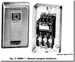
NEMA 1 General Purpose
The general purpose enclosure is intended primarily to prevent accidental contact with the enclosed apparatus. It is suitable for general purpose applications indoors where it is not exposed to unusual service conditions . A NEMA 1 enclosure serves as protection against dust and light indirect splashing, but is not dusttight (Fig. 3).
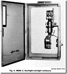
NEMA 3 Dusttight, Raintight
This enclosure is intended to provide suitable protection against specified weather hazards. A NEMA 3 enclosure is suitable for appli cation outdoors, on ship docks, canal locks, and construction work, and for application in subways and tunnels. It is also sleet-resistant (Fig. 4).
NEMA 3R Rainproof, Sleet Resistant
This enclosure protects against interference in operation of the contained equipment due to rain, and resists damage from exposure to sleet. It is designed with conduit hubs and external mounting, as well as drainage provisions.
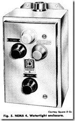
NEMA 4 Watertight
A watertight enclosure is designed to meet the hose test described below:
Enclosures shall be tested by subjection to a stream of water. A hose with one-inch nozzle shall be used and shall deliver at least 65gallons per minute. The water shall be directed on the enclosure from a distance of not less than 10feet and for aperiod of five minutes. During this period it may be directed in any one of more directions as desired. There shall be no leakage of water into the enclosure under these conditions.
A NEMA 4 enclosure is suitable for applications outdoors on ship docks and in dairies, breweries, etc. (Fig. 5).
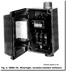
NEMA 4X Watertight, Corrosion-Resistant
These enclosures are generally constructed along the lines of NEMA 4 enclosures except they are made of a material that is highly resistant to corrosion. For this reason, they are ideal in applications such as paper mills, meat packing, fertilizer, and chemical plants, where contamin ants would ordinarily destroy a steel enclosure over a period of time. (Fig. 6).
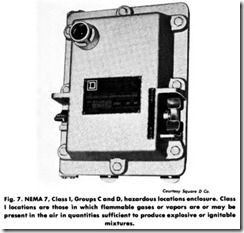
NEMA 7 Hazardous Locations, Class I
Here the design is to meet the application requirements of the NEC for Class I hazardous locations. In this type of equipment, the circuit interruption occurs in air. (Fig. 7).
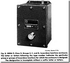
NEMA 9 Hazardous Locations, Class II
Class II locations are those which are hazardous because of the presence of combustible dust. This enclosure has been designed to handle the requirements of Class II. (Fig. 8).
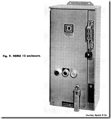
NEMA 12 Industrial Use
When it is necessary to exclude such materials as dust, lint, fibers and flyings, oil seepage, or coolant seepage, the NEMA 12 is required. There are no conduit openings or knockouts in the enclosure, and mounting is by means of flanges or mounting feet. (Fig. 9)
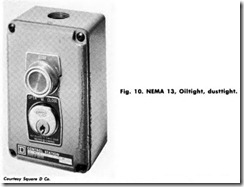
NEMA 13 Oiltight, Dusttight
This enclosure is usually made by casting. It has a gasket and can be used in the same atmospheres and locations as NEMA 12. The essential difference is that, due to its cast housing, a conduit entry is provided as an integral part of the enclosure. Mounting is by means of blind holes, rather than mounting brackets. (Fig. 10).
