Manual Push-Button Starters
Manual push-button line voltage starters are manufactured with two or three load contacts. The two-contact models are intended to control single-phase motors that
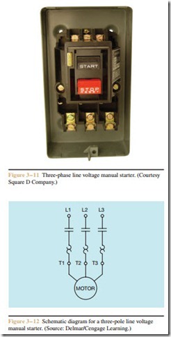
operate on 240 volts, or direct current motors. The starters that contain three contacts are intended to control three-phase motors. Push-button type manual starters are integral, not fractional, horsepower starters. Generally, they can control single-phase motors rated up to 5 horsepower, direct current motors up to 2 horse- power, and three-phase motors up to 10 horsepower. A typical three-contact manual push-button starter is shown in Figure 3–11. A schematic diagram for this type of starter is shown in Figure 3–12.
If any one of the overloads should trip, a mechanical mechanism will open the load contacts and dis- connect the motor from the line. Once the starter has tripped on overload, it must be reset before the motor can be restarted. After allowing enough time for the overload heaters to cool, the operator resets the starter by pressing the STOP push button with more than nor- mal pressure. This causes the mechanical mechanism to reset so that the motor can restart when the START push button is pressed. These starters are economical and are generally used with loads that are not started or stopped at frequent intervals. Although this type of starter provides overload protection, it does not provide low voltage release. If the power should fail and then be restored, the motor controlled by this starter will restart without warning.
Manual Starter with Low Voltage Release
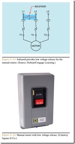
Integral horsepower manual starters with low volt- age release will not restart after a power failure without being reset. Resetting is accomplished by connecting a solenoid across the incoming power lines (Figure 3–13). As long as power is supplied to the starter, the solenoid holds a spring loaded mechanism in place. And as long as the mechanism is held in place, the load contacts can be closed when the START button is pressed. If the power should be interrupted, the spring loaded mechanism mechanically opens the contacts and prevents them from being re-closed until the starter has been manually reset. This starter will not operate unless power is present at the line terminal. This starter should not be confused with magnetic starters con- trolled by a coil. Magnetic type starters are designed to be used with other pilot control devices that control the operation of the starter. A manual starter with low volt- age release is shown in Figure 3–14.


