Magnetic and electro Magnetic applications
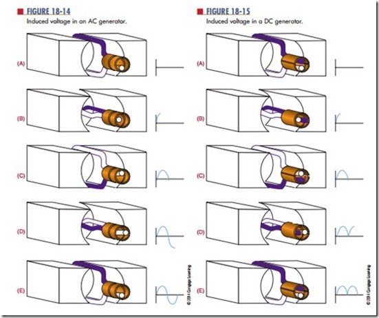
Figure 18-14 shows a loop of wire (conductor) being rotated (moved) in a magnetic field. The loop has a light and dark side for ease of explanation. At the point shown in part A, the dark half is parallel to the lines of force, as is the light half. No voltage is induced. As the loop is rotated toward the position shown in part B, the lines of force are cut and a voltage is induced. The induced voltage is greatest at this position, when the motion is at right angles to the magnetic field. As the loop is rotated to position C, fewer lines of force are cut and the induced voltage decreases from the maximum value to zero volts. At this point, the loop has rotated 180º, or half a circle.
The direction of current flow can be determined by applying the left-hand rule for generators. The arrow shows the direction of current flow at position B. When An alternating current (AC) generator converts mechanical energy to electrical energy by utilizing the principle of electromagnetic induction. The mechanical energy is needed to produce motion between the magnetic field and the conductor.
the loop is rotated to position D, the action reverses. As the dark half moves up through the magnetic lines of force and the light half moves down, applying the left-hand rule for generators shows that the induced voltage changes polarities. The voltage reaches a peak
at position D and decreases until the loop reaches the original position. The induced voltage has completed one cycle of two alternations.
The rotating loop is called an armature, and the source of the electromagnetic field is called the field. The armature can have any number of loops. The term armature refers to the part that rotates in the magnetic field, regardless of whether it consists of one loop or multiple loops. The frequency of the alternating current or voltage is the number of complete cycles completed per second. The speed of rotation determines the frequency. An ac generator is often called an alternator because it produces alternating current.
A DC (direct current) generator also converts mechanical energy into electrical energy. It functions like an AC generator with the exception that it converts the AC voltage to DC voltage. It does this with a device called a commutator, as shown in Figure 18-15. The output is taken from the commutator, a split ring. When the loop is rotated from position A to position B, a voltage is induced. The induced voltage is greatest as the motion is at right angles to the mag- netic field. As the loop is rotated to position C, the in- duced voltage decreases from the maximum value to zero. As the loop continues to rotate to position D, a voltage is induced, but the commutator reverses the output polarity so that it remains the same as before.
The loop then returns to the original position, E. The voltage generated from the commutator pulsates, but in one direction only, varying twice during each revolution between zero and maximum.
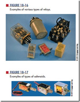
A relay is an electromechanical switch that opens and closes with an electromagnetic coil (Figure 18-16). As a current flows through the coil, it generates a magnetic field that attracts the plunger, pulling it down. As the plunger is pulled down, it closes the switch contacts. When the current through the coil stops, a spring pulls the armature back to its original position and opens the switch.
A relay is used where it is desirable to have one circuit control another circuit. It electrically isolates the two circuits. A small voltage or current can control a large voltage or current. A relay can also be used to control several circuits some distance away.
A doorbell is an application of the relay. The striker to ring the bell is attached to the plunger. As the door- bell is pressed, the relay coil is energized, pulling down the plunger and striking the bell. As the plunger moves down, it opens the circuit, de-energizing the relay. The plunger is pulled back by the spring closing the switch contacts, energizing the circuit again, and the cycle repeats until the button is released.
A solenoid is similar to a relay (Figure 18-17). A coil, when energized, pulls a plunger that does some mechanical work. This is used on some door chimes where the plunger strikes a metal bar. It is also used on automotive starters. The plunger pulls the starter gear in to engage the flywheel to start the engine.
Phonograph pickups use the electromagnetic principle. A magnetic field is produced by a permanent magnet that is attached to a stylus (needle). The permanent magnet is placed inside a small coil. As the stylus is tracked through the groove of a record, it moves up and down and from side to side in response to the audio signal recorded. The movement of the magnet in the coil induces a small voltage that varies at the audio signal response. The induced voltage is then amplified and used to drive a loudspeaker, reproduc- ing the audio signal.
loudspeakers are used for all types of audio amplification. Most speakers today are constructed of a moving coil around a permanent magnet. The magnet produces a stationary magnetic field. As current is passed through the coil, it produces a magnetic field that varies at the rate of the audio signal. The varying magnetic field of the coil is attracted and repelled by the magnetic field of the permanent mag- net. The coil is attached to a cone that moves back and forth in response to the audio signal. The cone moving back and forth moves the air, reproducing the audio sound.
Magnetic recording is used for cassette recorders, video recorders, reel-to-reel recorders, floppy disk drives, and hard disk drives. All these devices use the same electromagnetic principle to store information. A signal is stored on the tape or disk with a record head, to be read back later with a playback head. In some equipment, the record and playback head are combined in one package or they may be the same head. The record and playback head are a coil of wire with a ferromagnetic core. In a tiny gap between the ends of the core is a magnetic field. As the storage medium, a piece of material covered with iron oxide, is pulled across the record head, the magnetic field penetrates the tape, magnetizing it. The information is written on it in a magnetic pattern that corresponds to the original information. To play back or read the information, the medium is moved past the gap in the playback head. The changing magnetic field induces a small voltage into the coil winding. When this voltage is amplified, the original information is reproduced.
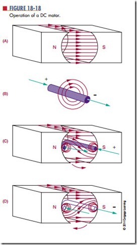
The operation of a DC motor (Figure 18-18) depends on the principle that a current-carrying conductor, placed in and at right angles to a magnetic field, tends to move at right angles to the direction of the field. Figure 18-18A shows a magnetic field extending between a north pole and a south pole. Figure 18-18B shows the magnetic field that exists around a current- carrying conductor. The plus sign implies that the cur- rent flows inward. The direction of the flux lines can be determined using the left-hand rule. Figure 18-18C
shows the conductor placed in the magnetic field. Note that both fields become distorted. Above the wire, the field is weakened, and the conductor tries to move up- ward. The amount of force exerted upward depends on the strength of the field between the poles and the amount of current flowing through the conductor. If the current through the conductor is reversed (Figure 18-18D), the direction of the magnetic flux around the conductor is reversed. If this occurs, the field below the conductor is weakened and the conductor tends to move downward.
A method of determining the direction of a current-carrying conductor in a magnetic field uses the right-hand motor rule: When the thumb, in- dex finger, and middle finger of the right hand are extended at right angles to each other, the middle finger points in the direction of current flow in the conductor; the index finger indicates the magnetic field from the north pole to the south pole; the thumb points in the direction of the motion of the conductor.
The force acting on a current-carrying conductor in a magnetic field depends on the strength of the magnetic field, the length of the conductor, and the amount of current flowing in the conductor. If a loop of wire, free to rotate horizontally, is placed between the two poles of a magnet, the loop spins as the poles repel each other. The current flows in one direction on one side of the loop and in the other direction on the other side of the loop. One side of the loop moves down and the other side of the loop moves upward. The loop rotates in a counterclockwise direction around its axis. A commutator reverses the direction of current flow in the loop every time it reaches the top or zero torque position. This is how a DC motor rotates. The loop or armature rotates in a magnetic field. Permanent magnets
or electromagnets may produce this field. The commutator reverses the direction of current through the armature. Note the resemblance between a DC motor and a dc generator.
The basic meter movement uses the principle of the DC motor. It consists of a stationary permanent magnet and a moveable coil. When the current flows through the coil, the resulting magnetic field reacts with the field of the permanent magnet and causes the coil to rotate. The greater the current flow through the coil, the stronger the magnetic field produced. The stronger the magnetic field produced, the greater the rotation of the coil. To determine the amount of current flow, a pointer is attached to the rotating coil. As the coil turns, the pointer also turns. The pointer moves across a graduated scale and indicates the amount of current flow. This type of meter movement is used for analog meters such as voltmeters, ammeters, and ohmmeters.
A conductor carrying a current can be deflected (moved) by a magnetic field. It is not the conductor that is deflected, but the electrons traveling in the conductor. The electrons are restricted to the conductor, so the conductor also moves. Electrons can travel through other media. In the case of television picture tubes, electrons travel through a vacuum to strike a phosphor screen where they emit light. The electrons are produced by an electron gun. By vary- ing the electron beam over the surface of the picture screen, a picture can be created. To move the beam back and forth across the screen, two magnetic fields deflect the beam. One magnetic field moves the beam up and down the screen, and the other magnetic field moves the beam from side to side. This method is used in television, radar, oscilloscopes, computer terminals, and other applications where a picture is desired on a screen.
Questions
1. What are the differences between an AC and a DC generator?
2. Why are relays important?
3. How does a loudspeaker produce sound?
4. What is the principle behind DC motors and meter movements?
How does an electromagnetic field produce an image on a screen?


