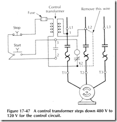
A magnetic motor starter may be operated from a control transformer supplied 24 V or 120 V system. This is of importance particularly for a large 460 V motor. A control transformer may step down the 460 V line voltage to 120 V. If the transformer is an integral part of the motor controller, it is permitted to be protected by fuses installed on the primary of the transformer, NEC Section 430 72(c). Fuseholders are usually supplied as an integral part of the transformer. The wiring of a transformer supplied control circuit is shown in Figure 17 47. The factory installed jumper wire between terminals X2 and L2 must be removed. (TheX2 marking on the motor controller can be seen in Figure 17 23.) The control electrical supply may be completely external to the motor branch circuit. A typical example would be a programmable controller operating a group of motors. The programmable controller output would most likely be 120 V to energize the motor starter coil. Figure 17 48 shows a motor starter operated from an external electrical supply


