Alternating Current Generator
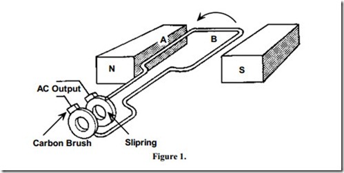
The basic principle of an AC generator is shown in Figure 1. The coil ends are connected to two slip rings.
As the coil sides A and B are rotated by an external force side A will have an EMF induced first in one direction and then in the other direction.
As side A of the coil is permanently connected to one slip ring, this ring will alternate from positive to negative as coil side A rotates past the North and South pole faces. The same process applies to coil side B. The generated output is therefore alternating ( AC ).
The direction of the induced EMF in each coil side can be determined by the use of Fleming’s Right Hand Rule.
Related posts:
2.4. SUMMARY of INDUCTION MACHINES: AN INTRODUCTION
Power Supply Design:High Current Power Supply Systems
Review of Electric Motor Maintenance and Troubleshooting
voltage:Voltage Sources
PC Hardware Interfaces: A Developer's Reference -Parallel Interface—The LPT Port
alternating Current:nonsinusoidal Waveforms
SYNCHRONOUS GENERATORS:OPERATION OF GENERATORS IN PARALLEL WITH LARGE POWER SYSTEMS
Temperature sensors and thermal transducers:Thermal to electrical transducers
THE UNIJUNCTION TRANSISTOR
INDUSTRIAL CONTROL ENGINEERING:INDUSTRIAL PROCESS CONTROLS
Software for Electronics:Productivity Software for electronics
Multispeed Multiwinding Motor
Measurement:The Acoustical Meaning of Harmonic Distortion
Environmental sensors:Wind-chill
