Insulation Resistance
This test is to ensure that there are no short circuits between live conductors or between live conductors and earth, and that there is no deterioration in insulation resistance caused by damage or dampness.
A direct voltage is applied, to test insulation resistance as the capacitive current quickly falls to zero so that it has no effect on the measurement. A high voltage is used because this will often break down poor insulation or surface leakage paths. In other words the high voltage may show up insulation weaknesses which would not be noticed at lower voltage levels.
An insulation resistance tester measures the applied voltage and the resulting leakage current flow. The resistance displayed, is obtained by an internal calculation based on Ohm’s Law.
As the effective capacitance of the system charges up, the leakage current reduces. A steady insulation resistance reading indicates that the cables are fully charged, and that the capacitive component of the test current has fallen to zero. If a wiring system is wet and / or dirty, the surface leakage component of test current will be high, giving a low insulation resistance reading.
Insulation resistances are all effectively connected in parallel. The total insulation resistance will therefore be lower than that of each individual circuit. In a large electrical installation, the total insulation resistance may be lower than that of a smaller installation.
Test Instrument Required
An insulation resistance tester ( having a DC test voltage which is dependent on the supply voltage in accordance with ETCI Rules ).
Warning:
Ensure that circuits are not live before commencing testing. Never turn the function dial whilst the test button is depressed. This may damage the instrument. Never touch the circuit under test during insulation resistance testing. Before testing always check the following:-
The “battery low” indicator is not showing.
There is no visual damage to the tester or test leads. Check the continuity of the test leads.
To check the continuity of the test leads:
Select the continuity function- and the lowest resistance range. Short the test leads together. The reading should be almost Zero Ohms.
An over-range ( OR ) indication will mean that the leads are faulty or the instrument fuse is blown.
Select the required test voltage ( 250 V, 500 V or 1000 V ) by rotating the function dial. Note:- The test voltage used for low voltage installations is 500 Volts.
Select the required range ( 20 M, 200 M, 2000 MΩ ) by rotating the range selector. Note:- Start on the highest range and only select a lower range if required.
Attach the test leads to the instrument and to the circuit to be tested. If the voltage warning bleeper sounds do not press the test button or the instrument will be damaged. Disconnect the instrument from the circuit. The circuit is live and must be de-energised before further testing. If all is well continue the test. The value of insulation resistance will be displayed in megohms.
Note:- The minimum acceptable resistance value is 1 MΩ. A new installation test may produce a reading in excess of 100 MΩ. If a reading of 2 MΩ or less is discovered, the reason should be investigated and corrected.
1t should be noted that the system charges up to the test voltage used. Thus it can be dangerous for people or animals to make contact with an electrical installation which is under test. Even when the test voltage is removed, the wiring system may remain charged for a significant time unless steps are taken to provide a path for discharge current.
When testing is complete ensure that the test button is released before the test leads are disconnected. This is because the system may be charged up and it must be allowed discharge through the test meter internal discharge resistor.
Pre Test Procedures and Observations.
1. The installation must be disconnected from the supply.
2. The Main Protective Conductor must be disconnected from the supply neutral.
3. All fuses are intact and all MCBs and switches are closed. ( exceptions as in 5 and 6 ).
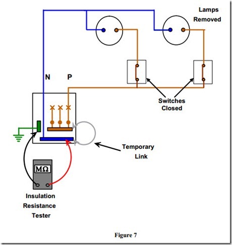
4. All current using equipment including lamps, pilot lights, bell transformers, smoke alarm units, PIR units, timers etc. are disconnected or otherwise excluded from the test between live conductors.
5. Note:- Where disconnection or removal of these items is impractical the control switches should be in the off position. Items left in circuit will cause false low readings.
6. Any equipment containing electronic circuitry must be disconnected or switched off in order to prevent damage by the high test voltage
Insulation Resistance between All Live Conductors and the Protective Conductor
Method
Connect all live and neutral conductors together at the distribution board and test between them and the protective conductor. The reading obtained should be 1 MW or greater.
An infinitely high resistance reading would be ideal.
Test of Insulation Resistance between all Live Conductors and the Protective Conductor
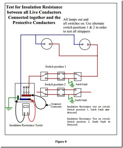
When testing two way or two way and intermediate lighting circuits, it is essential that both of the two way switches are switched over and the test repeated at each stage. This is to ensure that all strappers and the switch wire are included in the test.
Test for Insulation Resistance between all Live Conductors Connected together and the Protective Conductors
All lamps out and
all switches on. Use alternate switch positions 1 & 2 in order
to test all strappers
Switch position 1
Switch position 2
Earth Fault
Insulation Resistance Tester
Temporary Connection
Earth Fault
Insulation Resistance test on circuit. Switch position 1, Earth Fault not detected.
Insulation Resistance Test on circuit. Switch position 2, Earth Fault is Detected.
Figure 8
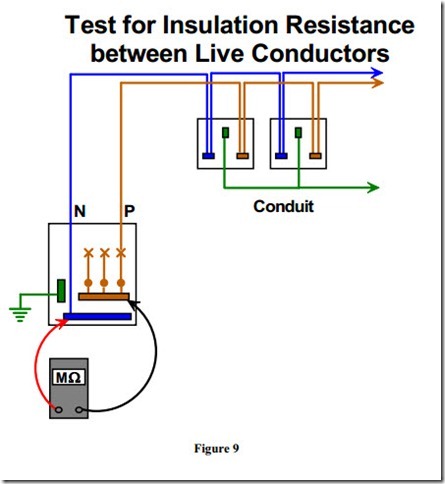
Insulation Resistance between Live Conductors
Method
Test between phase and neutral conductors. The reading obtained should be 1 MW or greater.
An infinitely high resistance reading would be ideal.


