 INDUCTION MOTOR TORQUE-SPEED CHARACTERISTICS
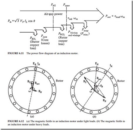
Figure 6.12a illustrates a squirrel-cage rotor of an induction motor that is operating at no load (near synchronous speed). The magnetization current IM flowing in the motor’s equivalent circuit (Fig. 6.7) creates the net magnetic field Bnet. Current IM and hence Bnet are propor- tional to E1. Since E1 remains constant with the changes in load, then IM and Bnet remain constant also. At no load (Fig. 6.12a), the rotor slip (the relative motion between the rotor
and the magnetic fields) and the rotor frequency are very small. Since the relative motion is small, the induced voltage in the rotor bars ER is very small and the resulting current IR is small. Also, since the rotor frequency is small (fr sfe), the reactance of the rotor (XR sXR ) is negligible, and the maximum rotor current IR is almost in phase with the rotor voltage ER.
The induced torque in this region is small (just enough to overcome the motor’s rota- tional losses) because the rotor magnetic field is quite small. When the motor is loaded down (Fig. 6.12b), the slip increases and the rotor speed falls. Now there is more relative motion between the rotor and the magnetic fields because the rotor speed is slower. Higher rotor voltage ER is now produced because of the higher relative motion. This in turn produces a larger rotor current IR.
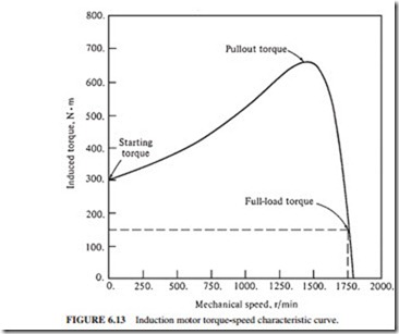
the resulting torque-speed characteristic is shown in Fig. 6.13. The torque-speed curve is divided into three regions. The first is the low-slip region. In this region, the motor slip
and mechanical speed change linearly with the load. The second region is the moderate-slip region. The peak torque (the pullout torque) of the motor occurs in this region. The third region is the high-slip region. In this region, the induced torque decreases with increasing load. Typically, the pullout torque is about 200 to 250 percent of the rated full-load torque of the machine. The starting torque (at zero speed) is about 150 percent of the full-load torque.
Comments on the Induction Motor Torque-Speed Curve
1. There is no induced torque at synchronous speed.
2. The torque-speed curve is linear between no load and full load. In this range, the rotor reactance is much smaller than the rotor resistance, so the rotor current, magnetic field, and induced torque varies linearly with slip.
3. There is a maximum possible torque that the motor cannot exceed. This torque is called the
pullout torque or breakdown torque and is 2 to 3 times the rated full torque of the motor.
4. The starting torque is about 150 percent of the full-load torque. The motor can start carrying any load that it normally handles at full power.
5. The motor torque is proportional to the square of the applied voltage.
6. If the motor turns backward, the induced torque will stop the rotor quickly and will try to rotate it in the opposite direction. Since switching any two of the stator phases will reverse the direction of magnetic field rotation, this fact can be used to stop motors quickly. This technique is known as plugging.
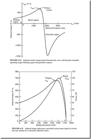
7. If the motor is driven beyond synchronous speed, it will operate as an induction gener- ator (Fig. 6.14).
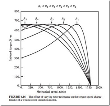
8. The variation of power converted to mechanical form (Pconv Tindwm) is shown in Fig. 6.15.
Variation of the Torque-Speed Characteristics
Figure 6.16 illustrates the variation of the torque-speed characteristic of a wound rotor induction motor. Recall that the resistance of the rotor circuit can be changed because the rotor circuit is brought out to the stator through slip rings. As the rotor resistance increases, the pull- out speed of the motor decreases, but the maximum torque remains constant. The advantage of this characteristic of wound rotor induction motors is the ability to start very heavy loads.
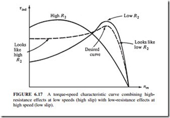
The maximum torque can be adjusted to occur at starting conditions by inserting a high resistance. Once the load starts to turn, the extra resistance can be removed from the circuit, and the maximum torque will shift up to near synchronous speed for normal operation. If the rotor is designed with high resistance, then the starting torque is high, but the slip is also high during normal operation. However, the higher the slip during normal operation, the smaller the fraction of power converted to mechanical power, and the lower the efficiency. A motor with a high rotor resistance has a high starting torque and poor efficiency during normal operation.
If the rotor resistance is low, then the starting torque is low and the starting current is high. However, the efficiency is high during normal operation. A compromise between high starting torque and good efficiency is needed.
A wound rotor induction motor can be used to provide high starting torque during start-up by inserting extra resistance. The extra resistance can be removed during normal operation to increase the efficiency. However, wound rotor induction motors are more expensive, require more maintenance, and have a more complex automatic control circuit than squirrel- cage induction motors. Also, wound rotor induction motors cannot be used in hazardous and explosive environments because completely sealed motors are needed. Figure 6.17 illustrates the desired motor characteristic.
