DEVELOPMENT OF THE INDUCTION MOTOR EQUIVALENT CIRCUIT
Stationary conditions
In Section 7.2 it was shown that, on a per-phase basis, the stationary induction motor is very much like a transformer, so to model the induction motor at rest we can use any of the transformer equivalent circuits we have looked at so far.
We can represent the motor at rest (the so-called ‘locked rotor’ condition) simply by setting Z 0 ¼ 0 in Figure 7.11. (For a wound-rotor motor we would have to increase RT to account for any external rotor-circuit resistance.) Given the applied voltage we can calculate the current and power that will be drawn from the supply, and if we know the eVective turns ratio we can also calculate the rotor current and the power being supplied to the rotor.
But although our induction motor resembles a transformer, its purpose in life is very diVerent because it is designed to convert electrical power to mechanical power, which of necessity involves movement. Our locked-rotor calculations will therefore be of limited use unless we can calculate the starting torque developed. Far more importantly, we need to be able to represent the electromechanical processes that take place over the whole speed range, so that we can predict the input current, power and developed torque at any speed. The remarkably simple and eVective way that this can be achieved is discussed next.
Modelling the electromechanical energy conversion process
In Chapters 5 and 6 we saw that the behaviour of the motor was determined primarily by the slip. In particular we saw that if the motor was unloaded, it would settle at almost the synchronous speed (i.e. with a very small slip), with very little induced rotor current, at very low frequency. As the load torque was increased the rotor slowed relative to the travelling Xux; the magnitude and frequency of the induced rotor currents increased; the rotor thereby produced more torque; and the stator current and power drawn from the supply auto- matically increased to furnish the mechanical output power.
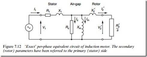
A very important observation in relation to what we are now seeking to do is that we recognised earlier that although the rotor currents were at slip frequency, their eVect (i.e. their MMF) was always reXected back at the stator windings at the supply frequency. This suggests that it must be possible to represent what takes place at slip-frequency on the rotor by referring the action to the primary (Wxed-frequency) side, using a transformer-type model; and it turns out that we can indeed model the entire energy-conversion process in a very simple way. All that is required is to replace the referred rotor resistance (R 0 ) with a Wctitious slip-dependent resistance (R 0 =s) in the short-circuited secondary of our transformer equivalent circuit.
Hence if we build from the exact transformer circuit in Figure 7.10(b), we obtain the induction motor equivalent circuit shown in Figure 7.12.
At any given slip, the power delivered to this ‘load’ resistance represents the power crossing the air-gap from rotor to stator. We can see straightaway that because the Wctitious load resistance is inversely pro- portional to slip, it reduces as the slip increases, thereby causing the power across the air-gap to increase and resulting in more current and power being drawn in from the supply. This behaviour is of course in line with what we already know about the induction motor.
We will see how to use the equivalent circuit to predict and illuminate motor behaviour in the next section, but Wrst there are two points worth making.
Stator Air-gap Rotor
Firstly, given the complexity of the spatial and temporal interactions in the induction motor it is extraordinary that everything can be properly represented by such a simple equivalent circuit, and it has always seemed a pity to the author that something so elegant receives little by way of commendation in the majority of textbooks.
Secondly, the following brief discussion is oVered for the beneWt of readers who are seeking at least some justiWcation for introducing the Wctitious resistance R 0 =s, though it has to be admitted that full treatment is beyond our scope. Pragmatists who are content to accept that the method works can jump to the next section.
The key to developing the representation lies in ensuring that the magnitude and phase of the referred rotor current (at supply frequency) in the transformer model is in agreement with the actual current (at slip frequency) in the rotor. We argued in Chapter 5 that the induced e.m.f. in the rotor at slip s would be sE2 at frequency sf, where E2 is the e.m.f. induced under locked rotor (s ¼ 1) conditions, when the rotor frequency is the same as the supply frequency, i.e. f. This e.m.f. acts on the series combination of the rotor resistance R2 and the rotor leakage reactance, which at frequency sf is given by sX2, where X2 is the rotor leakage reactance at supply frequency. Hence the magnitude of the rotor current is given by
In the supply-frequency equivalent circuit, e.g. Figure 7.9, the secondary
e.m.f. is E2, rather than sE2, so to obtain the same current in this model as given by equation (7.17), we require the slip-frequency rotor resistance and reactance to be divided by s, in which case the secondary current would be correctly given by


