APPROXIMATE EQUIVALENT CIRCUITS
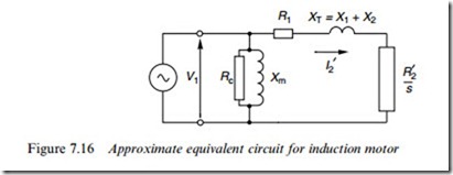
This section is devoted to what can be learned from the equivalent circuit in simpliWed form, beginning with the circuit shown in Figure 7.16, in which the magnetising branch has been moved to the left-hand side. This makes calculations very much easier because the current and power in the magnetising branch are independent of the load branch. The approximation involved in doing this are greater than in the case of a transformer because for a motor the ratio of magnetising reactance to leakage reactance is lower, but algebraic analysis is much simpler and the results can be illuminating.
A cursory examination of electrical machines textbooks reveals a wide variety in the approaches taken to squeeze value from the study of the approximate equivalent circuit, but in the author’s view there are often so many formulae that the reader becomes overwhelmed. So here we will
focus on two simple messages. Firstly, we will develop an expression that neatly encapsulates the fundamental behaviour of the induction motor, and illustrates the trade-oVs involved in design; and secondly we will examine how the relative values of rotor resistance and reactance inXu- ence the shape of the torque–speed curve.
Starting and full-load relationships
Straightforward circuit analysis of the circuit in Figure 7.16, together with equation (7.20) for the torque yields the following expressions for the load component of current (I 0 ) and for the torque per phase:
The second expression (with the square of voltage in the numerator) reminds us of the sensitivity of torque to voltage variation, in that a 5% reduction in voltage gives a little over 10% reduction in torque.
If we substitute s = 1 and s = sX in these equations we obtain expressions for the starting current, the full-load current, the starting torque and the full-load torque. Each of these quantities is important in its own right, and they all depend on the rotor resistance and reactance. But by combining the four expressions we obtain the very far-reaching result given by equation (7.23) below.
The left-hand side of equation (7.23) is the ratio of starting torque to full-load torque, an important parameter for any application as it is clearly no good having a motor that can drive a load once up to speed, but either has insuYcient torque to start the load from rest, or (perhaps less likely) more starting torque than is necessary leading to a too rapid acceleration.
On the right-hand side of equation (7.23), the importance of the ratio of starting to full-load current has already been emphasised: in general it is desirable to minimise this ratio in order to prevent voltage regulation at the supply terminals during a direct-on-line start. The other term is the full-load slip, which, as we have already seen should always be as low as possible in order to maximise the eYciency of the motor.
The remarkable thing about equation (7.23) is that it neither contains the rotor or stator resistances, nor the leakage reactances. This under- lines the fact that this result, like those given in equations (7.20) and (7.21), reXects fundamental properties that are applicable to any induction motor.
The inescapable design trade-oV faced by the designer of a constant-frequency machine is revealed by equation (7.23). We usually want to keep the full-load slip as small as possible (to maximise eYciency), and for direct starting the smaller the starting current, the better. But if both terms on the right-hand side are small, we will be left with a low starting torque, which is generally not desirable, and we must therefore seek a compromise between the starting and full-load performances, as was explained in Chapter 6.
It has to be acknowledged that the current ratio in equation (7.23) relates the load (rotor branch) currents, the magnetising current having been ignored, so there is inevitably a degree of approximation. But for the majority of machines (i.e. 2-pole and 4-pole) equation (7.23) holds good, and in view of its simplicity and value it is surprising that it does not Wgure in many ‘machines’ textbooks.
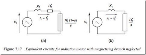
Dependence of pull out torque on motor parameters The aim here is to quantify the dependence of the maximum or pull-out torque on the rotor parameters, for which we make use of the simplest possible (but still very useful) model shown in Figure 7.17. The magnet- ising branch and the stator resistance are both ignored, so that there is only one current, the referred rotor current being the same as the stator current I1. Of the two forms shown in Figure 7.17, we will focus on the one in Figure 7.17(b), in which the actual and Wctitious rotor resistances are combined.
Most of the discussion will be based on normal operation, i.e. with a constant applied voltage at a constant frequency. In practice both leakage
reactance and rotor resistance are parameters that the designer can con- trol, but to simplify matters here we will treat the reactance as constant and regard the rotor resistance as a variable.
We will derive the algebraic relations Wrst, then turn to a more illuminating graphical approach. To obtain the torque–slip relationship we will make use of equation (7.20), which shows that the torque is directly proportional to the total rotor power. Throughout this section our main concern will be with how motor behaviour depends on the slip, particularly over the motoring region from s =0 to s = 1. (The treatment can easily be extended to cover the braking and generating regions, but they are not included here.)
Analysis
The total rotor power per phase is given by
The bracketed expression on the right-hand side of equation (7.24) indicates how the torque varies with slip.
At low values of slip (i.e. in the normal range of continuous operation) where sX is much less than the rotor resistance R 0 , the torque becomes proportional to the slip and inversely proportional to the rotor resistance. This explains why the torque–speed curves we have seen in Chapters 5 and 6 are linear in the normal operating region, and why the curves become steeper as the rotor resistance is reduced.
At the other extreme, when the slip is 1 (i.e. at standstill), we usually Wnd that the reactance is larger than the resistance, in which case the bracketed term in equation (7.24) reduces to R 0 =X 2. The starting torque is then proportional to the rotor resistance, a result also discussed in Chapters 5 and 6.
By diVerentiating the bracketed expression in equation (7.24) with respect to the slip, and equating the result to zero, we can Wnd the slip at which the maximum torque occurs. The slip for maximum torque turns out to be given by
(A circuit theorist could have written down this expression by inspection of Figure 7.17, provided that he knew that the condition for maximum torque was that the power in the rotor was at its peak.) Substituting the slip for maximum torque in equation (7.24), and using equation (7.21) we obtain an expression for the maximum torque per phase as:
From these two equations we see that the slip at which maximum torque is developed is directly proportional to the rotor resistance, but that the peak torque itself is independent of the rotor resistance, and depends inversely on the leakage reactance.
Graphical interpretation via phasor diagram
We will look at the current phasor diagram as the slip is varied, for two motors, both having the same leakage reactance, XT. One motor will be representative of the ‘low-resistance’ end of the scale (R 0 ¼ 0:1XT) while the other will represent the ‘high-resistance’ end (R 0 ¼ XT). As before, the voltage and frequency are constant throughout.
The reason for choosing total leakage reactance as the common factor linking the two motors is simply that the current loci (see below) are then very similar, and the peak torques are the same, which makes it easier to compare the shapes of the torque–slip curves.
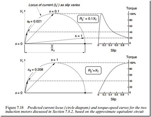
The locus of the load current phasors as the slip varies is shown on the left-hand side of Figure 7.18, while on the right-hand side the torque– slip curves are shown.
The locus of current with slip is semicircular, the motoring condition extending only over the range from s ¼ 0 to s ¼ 1. The point corre- sponding to s ¼ inWnite is important because it deWnes the diameter of the locus as V =XT: it is shown by the dot on the horizontal axis. The
remainder of the circular locus (not shown) corresponds to negative slip, i.e. generator action.
The torque is proportional to total rotor power input, and the rotor power input is given by Prot ¼ V1I 0 cos f , where f is the rotor power-factor angle, i.e. the angle between the referred rotor current and the voltage. Since the voltage is constant and I 0 cos f is the ‘in-phase’ component of current, i.e. the vertical component in Figure 7.18, it follows that the torque is directly proportional to the projection of the current phasor onto the voltage, i.e. to the height of the tip of the current above the horizontal line through the point marking s ¼ 0. This has been emphasised in Figure 7.18 by drawing the adjacent torque–slip curves to a scale calibrated in terms of the peak (pull-out) torque, the value of which is determined by the radius of the circle, as indicated in equation (7.26). These curves conWrm the Wnding in equation (7.25) that the peak torque is reached when the slip is equal to the ratio of rotor resistance to reactance.
We note that although the high-resistance motor has a lower starting
current, it produces a much greater starting torque because the current lags the voltage by only 458 compared with over 848 for the low- resistance motor. On the other hand the gradient of the torque–slip curve in the normal operating region is much steeper for the low-
resistance motor, so its speed holding as the load changes is better and full-load eYciency can be correspondingly higher. As explained in Chap- ter 6, these widely diVering characteristics indicate the need to match motor to application.
For the sake of completeness, full-load conditions have also been shown, based on an arbitrarily chosen speciWcation that the full-load torque is 40% of the pull-out torque, i.e. Tpo=TX ¼ 2:5. With this constraint, the full-load slips and full-load currents can be calculated using equation (7.21), and thus we can draw up a table summarising the comparative performance of the two motors.
The full-load points are marked on Figure 7.18: the continuous operating region (from no-load to full-load) occupies the comparatively short section of the locus betweens s ¼ 0 (no-load) to the full-load slip in each case.
As already observed, the starting and low-speed performance of the high-resistance motor is superior, but its full-load rotor eYciency is very poor and rotor heating would prevent continuous operation at a slip as high as 21% (unless it was a slipring machine where most of the resist- ance was external). At normal running speeds the low resistance motor is superior, with its much greater rotor eYciency and steep torque–speed curve; but its starting torque is very low and it could only be used for fan-type loads, which do not require high starting torque.
As explained in Chapter 6, the double-cage rotor or the deep-bar rotor combines the merits of both high- and low-resistance rotors by having an outer cage with high resistance and relatively low reactance, in which most of the mains frequency starting current Xows, and an inner cage of relatively low resistance and high reactance. The latter comes into eVect as the speed rises and the rotor frequency reduces, so that at normal speed it becomes the dominant cage. The resulting torque–speed curves – shown typically in Figure 6.9 – oVer good performance over the full speed range.
Equivalent circuits for double-cage motors come in a variety of guises, all using two parallel rotor branches, with a variety of methods for taking account of the signiWcant mutual inductance between the cages.
Treatment of double-cage induction motor circuits is best left to more specialist textbooks.


