Some methods of identifying unmarked leads require running the motor on part of its winding. Motors with concentric-shaped coils won’t start by themselves on part of their winding. The shaft has to be spun to start them, which is dangerous. Voltage readings must be taken from the leads with the motor running. (This is also dangerous.)
The following method is much safer and simpler. (Use the comparison test on all circuits to be sure there is no winding failure.)
Identifying Unmarked Leads in a Wye Connection
The following equipment is needed:
• Test light or ohmmeter
• Low-voltage DC source (6- or 12-volt battery)
• Low-scale DC voltmeter (must be analog) Numbered lead labels
The motor must be assembled (the rotor is needed to complete the magnetic circuit).
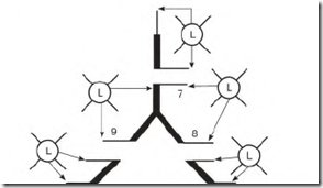
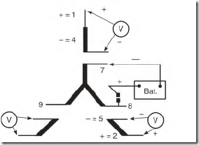
The first step is to separate the circuits by using an ohmmeter or test light. As can be seen in Fig. 6.17, there are three sets of two leads that light together and one set of three leads. Pair off the sets of two. Permanently label the leads in the set of three with numbers T7, T8, and T9 as shown.
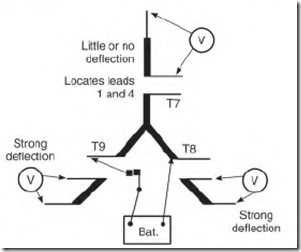
Next, locate Tl and T4. Connect one of the DC voltage-source leads to T8, then make and break (flash) the circuit by intermittently touching the other lead to T9. Check across all three (two-lead) sets with the voltmeter while flashing T9. The voltmeter will show a strong deflection on two of the pairs and little or no deflection on one pair (Fig. 6.18). The pair with little
FIGURE 6.17 Identifying the circuits of a nine-lead wye-connected motor with unmarked leads. The set with three leads is permanently labeled 7, 8, and 9.
FIGURE 6.18 The battery connection for locating Tl and T4.
or no deflection is Tl and T4—located but not identified—and is part of the T7 phase.
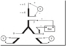
Attach the voltmeter to the located pair. Attach the voltage source to T7 and T8 with the positive lead on T7 (Fig. 6.19). Flash the circuit. If the voltmeter deflects upscale, permanently label the motor lead that is connected to the positive voltmeter probe T 1, and its paired lead T4.
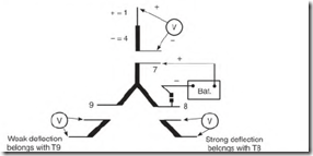
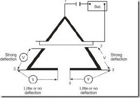
With the voltage source still at this location (flashing T7 and T8), check the other two pairs with the voltmeter. The pair with a strong deflection will belong to T8, and the pair with little or no deflection to T9 (Fig. 6.20).
Connect the voltmeter to the pair with a strong deflection (Fig. 6.21).
Attach the voltage source to T7 and T8 (with the positive probe on T8).
While flashing the circuit (if there is an upscale deflection), permanently
FIGURE 6.19 The connection for identifying Tl and T4.
FIGURE 6.20 The battery connection for locating T2 and T5 and also T3 and T6.
FIGURE 6.21 The connection for identifying T2 and T5.
label the motor lead connected to the positive voltmeter probe T2 and its paired lead T5.
Repeat the preceding procedure—with the positive probe of the voltage source on T9—to identify the last pair (T3 and T6).
In the preceding test, two of the three phases had half of their windings energized, and one complete phase winding was idle. The pair of leads (belonging to the idle phase) had little or no deflection, because its winding wasn’t in the same magnetic circuit (angle) as the energized phases. (The idle winding is offset 120 electrical degrees from the others.)
Identifying Unmarked Leads in a Delta Connection
This equipment is needed:
• Test light or ohmmeter
• Low-voltage DC source (6- or 12-volt battery)
• Low-scale DC voltmeter (must be analog)
• Numbered lead labels
The motor must be assembled because the rotor is needed to complete the magnetic circuit.
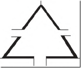
First, separate the circuits. As can be seen in Fig. 6.22, there are three sets of three leads that light to each other.
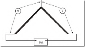
Next locate the center leads (delta points) of each circuit. (The points of the delta connection—leads T 1, T2, and T3—often have larger wire than the
FIGURE 6.22 Identifying the circuits of a nine-lead delta-connected motor with unmarked leads.
FIGURE 6.23 The connection for identifying the points T1, T2, and T3 of the delta connection.
other six leads.) Attach a DC voltage source to any two leads of any threelead circuit. There will be a voltage from both voltage source leads—to the point—as shown in Fig. 6.23, if the right leads are selected.
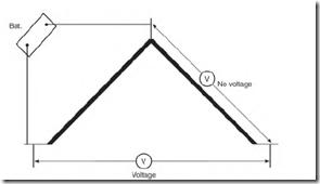
If the point is one of the leads attached to the power source, there will be a voltage read from one source lead to the idle lead and none from the other source lead (Fig. 6.24).
Permanently label the delta points T 1, T2, and T3.
Thrist the two leads that belong to point Tl together, and apply intermittent DC voltage, as shown in Fig. 6.25. From point T2, one lead (of its three-lead circuit) will show a strong deflection, and the other lead will
FIGURE 6.24 If the wrong pair is energized, one lead will have no voltage.
FIGURE 6.25 Power applied to Tl and its internally connected pair identifies T7 and T5.
show little or no deflection. Permanently label the strong deflection lead T7 and the other T5.
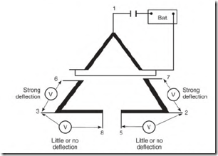
From point T3 (Fig. 6.26), one lead (of its three-lead circuit) will show a strong deflection, and the other lead will show little to none. Permanently label the strong deflection lead T6 and the other T8.
Little or no Little or no deflection deflection
FIGURE 6.26 The voltmeter connection for identifying T8 and T6 and and T7
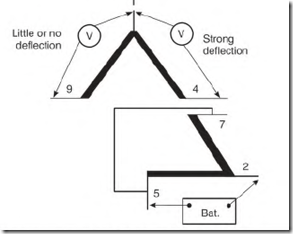
FIGURE 6.27 The connection for identifying T4 and T9.
Connect leads T5 and T7 as shown in Fig. 6.27 and apply intermittent
DC.
From point T 1, one lead (of its three-lead circuit) will show a strong deflection, and the other lead will show little or none. Permanently label the strong deflection lead T4 and the other T9.
Identifying unmarked leads with the delta connection involves deflection of the voltmeter needle—not polarity as with wye. Half of the two phases that are energized in this procedure are idle. Their windings are cut by the lines of force of the energized half. This produces a strong deflection.
The windings of the idle phase are out of the magnetic circuit and aren’t cut by lines of force. Very little or no voltage is transformed into them.
Very helpfull thank you very much