DEFINITION OF TERMS
Bore and Stroke
Bore is the diameter of the cylinder in inches. Stroke is the distance the piston moves between upper and lower dead center in inches.
Piston Displacement
Piston displacement for one cylinder is the cubic volume through which the piston sweeps in moving the length of one stroke. This volume in cubic inches multiplied by the number of cylin ders gives the piston displacement of the whole ‘ engine. This total piston displacement indicates the “size” of the engine. Piston displacement may be figured by means of the following simple for mula:
Piston displacement equals bore X bore X stroke X number of cylinders X .785. All other things being equal, the piston dis placement of an engine is an index of the power it may be expected to produce.
Engine Torque
Engine torque or turning effort is the rotating force developed at the flywheel. In the case of a typical automobile engine this force might be 200 pounds when measured at a radius of one foot from the center of the flywheel. When the torque radius is one foot it is customary to say that the torque developed by an engine is 200 pounds-feet. This term should not be confused with foot pounds although there is a relationship between them, namely one pound-foot of torque during one revolution represents 6.28 foot-pounds of me chanical energy.
Brake Horsepower
Brake horsepower is the actual horsepower of the engine delivered at the flywheel. Many years ago it was customary to measure horsepower by a device called a Prony brake (named after the man who invented it) -hence the term brake horse power. Today, however, horsepower is deter mined by a dynamometer of which there are several types. Both the Prony brake and the dy namometer measure torque. The horsepower is calculated from the torque.
By definition one horsepower represents the production of 33,000 foot-pounds of mechanical energy per minute. Therefore horsepower equals foot-pounds per minute divided by 33,000. Foot pounds may be defined as the mechanical energy developing by a force of so many pounds acting through a certain distance per minute. Thus a force of, say, 33,000 pounds acting through a distance of ten feet in one minute would represent 330,000 foot-pounds or 10 hp ( 330,000/33,000).
When an engine is tested on a dynamometer, if it develops 200 pounds-feet of torque it delivers 200 X 6.28 foot-pounds of mechanical energy perrevolution or 1256 foot-pounds ( 200 X 6.28).
If the engine is running 1,000 rpm, the foot pound production per minute is 1,256,000 foot pounds ( 1256 X 1,000) or 38 hp ( 1,256,000/ 33,000).The torque is measured at various other engine speeds from, say, 500 to 4,000 rpm and the horse power for each speed is calculated.
Taxable Horsepower
In some states, automobiles are taxed according to a taxable horsepower rating based on the fol lowing formula:
Taxable horsepower equals bore X bore X number of cylinders X .4.
This ancient formula was fairly true 40 years ago but has no relationship to the horsepower production of modern engines. The taxable horse power formula is often called the S.A.E. horse power formula but the Society of Automotive Engineers had nothing to do with it. The formula was originated by The Royal Automobile Club of England.
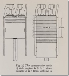
VOLUME 8 Fig. 10 The compression ratio of this engine is 8 to 1 since volume B is 8 times volume A STROKE
Compression Ratio
Compression ratio is the ratio between the total volume of the interior of a cylinder with the piston at bottom dead center divided by the volume at top dead center, Fig. 10. For example, in a given engine the total volume with piston at bottom dead center might be 80 cubic inches while the volume at top center might be 10 cubic inches, in which case the compression ratio would be 8 to 1 ( 80/10). Piston displacement is the difference between these two volumes or 70 cubic inches.
Another way of expressing compression ratio is as follows: Determine the volume of the com bustion chamber with piston at top dead center say this volume is 10 cubic inches for example and that the calculated piston displacement is 70 cubic inches. Therefore the compression ratio is
Compression ratios on modern cars range from 7.50 to 1 up to 11.0 or more. Power and fuel economy are increased as the compression ratio is raised.
Other things being equal, the higher the compression ratio the higher the compression pressure obtained at the end of the compression stroke. Compression pressures on modern cars range roughly from 110 to 200 pounds per square inch on open throttle. In a given make and model of engine, compression pressure is a maximum at some certain speed, say, 1,800 rpm, for example. Above and below this speed the compression pressure falls off gradually. Maximum torque is produced when compression pressure is at maxi mum. Compression pressure is reduced as the throttle is closed, being about 35 pounds at idling speed.
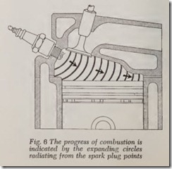
When the spark ignites the mixture, combustion should proceed smoothly in expanding circles, Fig. 6, until all the mixture in the combustion chamber is consumed. Pressure in the combustion chamber rises as combustion proceeds and reaches a maximum about the time all of the mix ture is burned. The higher the compression pres sure the greater the maximum combustion pres sure.
Detonation
The preceding paragraph describes normal com bustion. However, under certain conditions, after combustion has proceeded part way through the chamber, the remaining mixture may go off with a bang like so much dynamite. This explosion causes a sharp rise in pressure which shakes the cylinder head and causes the head to vibrate with the result that a metallic knock is heard. The phenomenon just described is called detonation. Detonation (pinging) occurs only when the throt tle is wide open or nearly so and it is _more likely to occur at moderate engine speed ( 15 to 20 mph) than at high engine speed.
There are certain factors that encourage detona tion and others that discourage or completely eliminate it. Factors that encourage detonation include high compression pressure resulting from high compression ratio. A hot spot in the combus tion chamber such as an unduly hot exhaust valve, piston head, cylinder head, and so forth. Severe detonation will be heard when the cooling water is boiling in the cylinder head or when there is no water in the head. A heavy coating of carbon on cylinder head or piston head may cause detona tion. The carbon prevents adequate cooling of the surfaces and thus detonation is encouraged. Car bon also increases the compression ratio which in turn encourages detonation. If the spark occurs too early as the piston moves upward on its compression stroke, detonation will result. All the factors mentioned in this paragraph including high compression pressure increase the tempera ture of the mixture and the higher the mixture temperature the greater is the tendency to deto nate. Also, the lower the octane number of the fuel the more likely it is that detonation will take place. A lean mixture encourages detonation.
On the other hand, detonation can be satisfac torily suppressed or eliminated by using a suffi ciently high octane fuel; by reducing the compres sion pressure; by timing the spark so that it occurs at the proper instant rather than too soon; by keeping the combustion chamber surfaces adequately cool, and free of carbon.
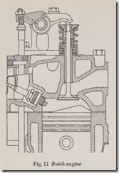
Usually detonation does not occur until most of mixture has been burned. Therefore, if this mix ture is cooled somewhat its detonation is avoided. Cooling this last portion of the mixture is obtained by suitable combustion chamber design. In the case of the combustion chamber shown in Fig. 6, by the time the flame front has reached the valve area the burned gases have a pressure of 400 to 600 pounds per square inch and that therefore the remaining unburned gas has likewise been com pressed to this high figure. Therefore, the remain ing mixture is quite hot because mixture tempera ture increases with pressure. But then the mixture encounters the comparatively cool cylinder head and piston head where its temperature is reduced below the detonating point. The same result can be obtained by bulging the piston head upward, Fig. 11, so that the last portion of the mixture to burn is forced into close contact with the cylinder head and piston head, and in this way the remain ing mixture is cooled below the detonation point.
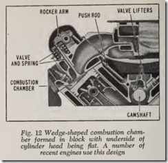
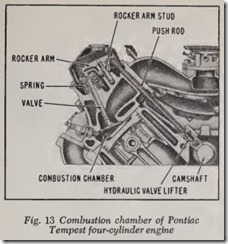
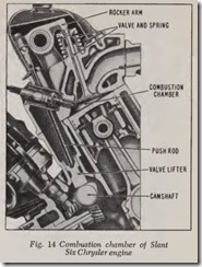
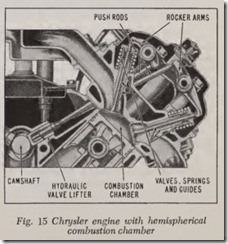
Other examples of combustion chamber design are shown in Figs. 12 to 15.
Spark Knock and Pre-Ignition
Spark knock, as previously indicated, is caused by allowing the spark to occur too early. Pre-igni tion is caused by a red hot spot in the combustion cham her. Such a spot might be a piece of carbon which is hot enough to ignite the mixture before the spark occurs, or a red hot spark plug, red hot exhaust valve or gasket edge too hot.
REASONS FOR COOLING SYSTEM
Cylinder block, cylinder head, piston and rings plus valves must be kept reasonably cool for a variety of reasons. Likewise these parts must be lubricated. The maximum allowable working tem perature of the different parts varies, which means that an exhaust valve head may perform satisfac torily at 1200 degrees F or higher whereas numer ous other engine parts must not exceed half this temperature.
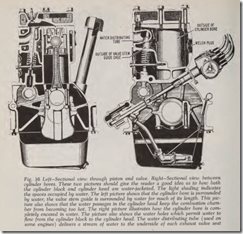
Cooling, lubrication and combustion are tiedtogether. Except in the Corvair engine, cooling in modern American automobiles is obtained first by circulating water through jackets which surround the cylinder bore and jackets within the cylinder head. The piston , piston rings, valves and other parts are cooled by their contact with the cylinder block.
The water in the cooling system when the engine is warm usually has a temperature ranging from 150 to 195 degrees F. The piston is cooled by its contact with the cylinder bore, Fig. 16, as well as by the contact of the rings with the bore.
The valves are cooled partly by the contact of the valve stem with its guide and partly by the contact of the valve face with the cylinder block whenever the valve is seated. Good contact between valve and seat is most important for satis factory valve cooling.
Too high temperature of the cooling water may r esult in knocking or pinging of the engine onwide open throttle.
Excessive piston or ring temperature may result in the destruction of the lubricant. There are two stages: ( 1) The oil rnay become gummy and therefore cause piston rings to stick in their grooves with the result that the rings are no longer able to seal the piston to its bore or gum may cause valve stems to stick in their guides. ( 2) The temperature may be high enough to drive the hydrogen out of the oil. In this case, since oil is composed of hydrogen and carbon, a carbon de posit is left wherever the excessive temperature occurs. In other words the oil chars.
The points where carbon (or gum) may be deposited include piston rings and grooves, slots in oil control rings, piston head, cylinder head, exhaust valve face and seat, valve stems and guides. Excessive carbon deposit on cylinder head or piston head may result in detonation or pre ignition. Carbon deposit on the porcelain insulator of a spark plug will prevent ignition if the high tension current flows across the carbon film on the insulator instead of jumping between the spark plug points. Carbon (or dust) deposited on the face of the exhaust valve or its seat will prevent it from seating tightly. The resulting leakage of hot exhaust gases through the opening will eventually burn both the exhaust valve and its seat and in creased leakage will result.
The operation of the cooling system on the Corvair is described in the Cooling System Chap ter. Suffice it to say here that the engine is a horizontally-opposed, air-cooled six-cylinder type. The two aluminum cylinder heads incorporate cooling fins as do the individual cylinders.
CYLINDER NUMBERING
In speaking of the various cylinders in an engine it is customary to assign number s to them, running from front to rear ( Corvair excepted). Therefore the cylinders in a four-cylinder engine are designated 1-2-3-4, in an In-Line six they are 1- 2-3-4-5-6 and similarly the cylinders in an In-Line eight are 1-2-3-4-5-6-7-8. In a V8 a similar system may be used by adding the letters R and L for right and left blocks, respectively. Therefore, in a V8 the cylinders in the right block (or bank) would be called 1R, 2R, 3R, 4R. With the excep tion of the Corvair the terms right and left in an automobile mean right and left as viewed from the driver’s seat.
In the Corvair, which has the engine in the rear, the right rear cylinder is # 1 and the left rear cylinder is #2. Thus reading in order from the rear, the right bank is numbered 1-3-5 and the left bank is 2-4-6.
However, there is obviously another way of numbering a V engine and that is to call the first cylinder in the left block No. 1 and continue through this block consecutively. The numbers for the right block then run consecutively after the left block. In this case, for example, the cylinders in a V8 would be numbered 1-2-3-4 for the left block and 5-6-7-8 for the right block. Still another way of numbering cylinders in a V engine is to use odd numbers for one bank and even numbers for the other, in which case one bank in a V8 would be numbered 1-3-5-7 and the other bank 2-4-6-8.
The method of numbering V engines is a choice made by the car maker and all his instructions concerning service work on the various cylinders is based on the numbering system which has been chosen. The numbering system involves various service operations including ignition work and valve adjustment, and so forth. With respect to V engines it is quite necessary to know the car maker’s numbering system before the service op erations can be intelligently performed.
FIRING ORDER
The sequence in which the cylinders fire is called the firing order. There are two possible firing orders for an in-line four cylinder engine, namely 1-2-4-3 and 1-3-4-2. However, the latter, 1- 3-4-2 is the one that is used almost without exception. ‘The firing order also indicates the order in which the intake valves open and close; also the exhaust valves.
When an engine is designed, the firing order is determined by the position of the cams on the camshaft which means that the intake and exhaust ca’ms are positioned, in a four cylinder
engine, for example, to give either a firing order of 1-2-4-3 or 1-3-4-2. In the case of a four cylinder engine, it makes no difference which of these two firing orders is chosen, but in engines with more cylinders, the firing order makes a considerable difference.
The reason for this is that the mixture of gaso line and air in the intake manifold has a certain amount of inertia, and it is undesirable to change its direction of flow more than is necessary. So every effort is made to arrange the intake mani fold and the firing order so that there is as little interference with gas flow as possible. Similarly with the exhaust gases. Certain combinations of exhaust gas flow can cause increased back pres sure in the system, resulting in reduced power output. Other combinations can produce much increased power. So the firing order and exhaust system are designed to give the best possible result.
When the firing order is determined, the high tension cables from the distributor cap to the spark plugs must be attached according to the order demanded by the camshaft.
Except for the Corvair, Buick and Oldsmobile V-6 engine, all six cylinder passenger car engines have a firing order of 1-5-3-6-2-4, with the num bers running from front to rear. There is only one exception to this rule. The Jaguar engine has the same firing order but the cylinders are numbered from rear to front, with the No.1 at the rear.
The Corvair firing order is 1-4-5-2-3-6 with numbering system as described above, while the Buick and Olds V-6 uses 1-6-5-4-3-2, with the left bank of cylinders numbered 1-3-5, starting from the front, and the right bank 2-4-6.
The majority of V-8’s use a firing order of 1-8-4-3-6-5-7-2, with the left bank of cylinders num bered 1-3-5-7 and the right bank 2-4-6-8, again starting from the front. Exceptions are:
Buick 401 and 425 cu. in. engines of 1963 thru 1966, which use a firing order of 1-2-7-8-4-5-6- 3, with the right bank of cylinders numbered 1-3-5-7 and the left bank 2-4-6-8.
Cadillacs from 1963 thru 1967 had a firing order of 1-8-7-2-6-5-4-3, with odd cylinder numbers in the left bank, even numbers in the right.
Cadillacs from 1968 onwards have a firing order of 1-5-6-3-4-2-7-8, with odd numbers in the right bank and even numbers in the left.
Ford and Mercury engines use a firing order of 1-5-4-2-6-3-7-8, with cylinders 1-2-3-4 in the right bank, and 5-6-7-8 in the left bank. The exception is the 351 and 400 cu. in. engine, which has a firing order of 1-3-7-2-6-5-4-8 with the same cylinder numbering system. Pre 1959 engines used 1-5-4-8-6-3-7-2.
Oldsmobile 394 cu. in. engine has a firing order of 1-8-7-3-6-5-4-2, with odd numbers in the left bank, even numbers in the right.
